

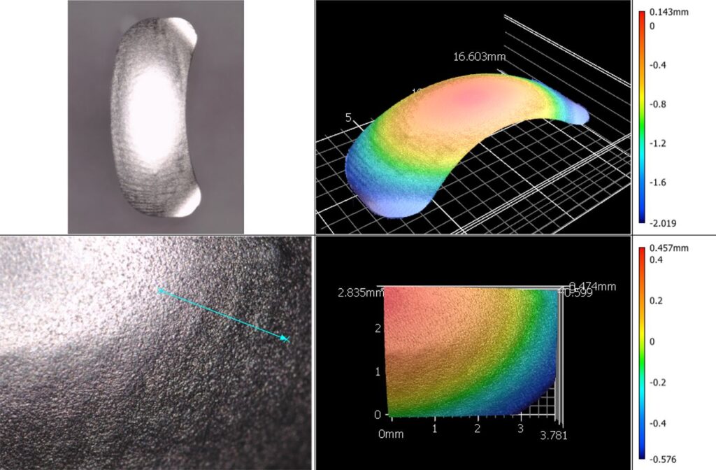
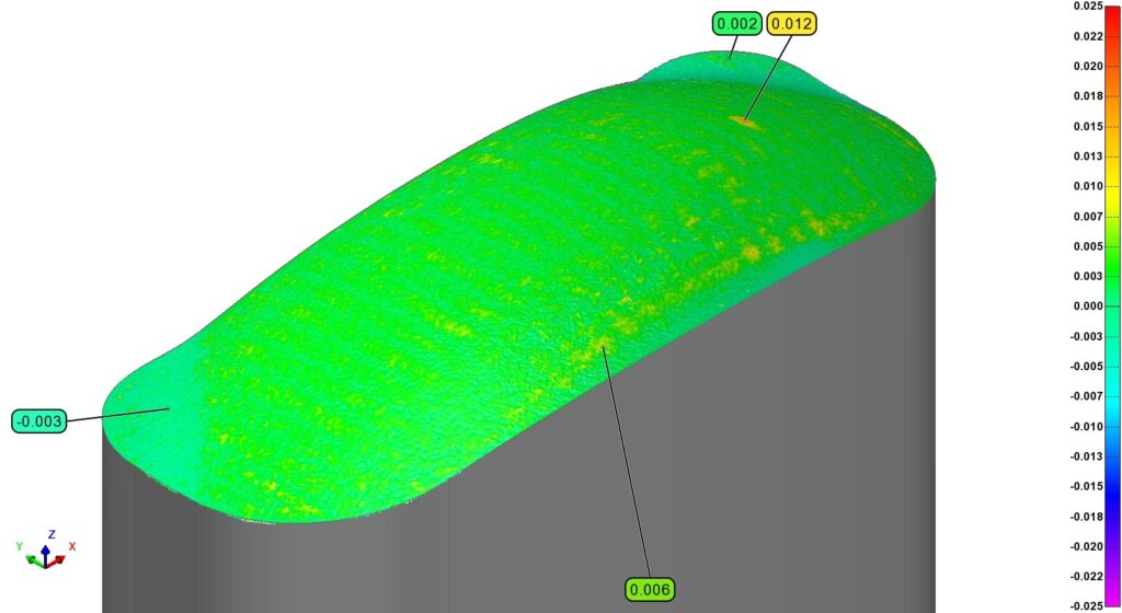

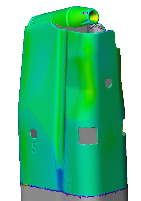

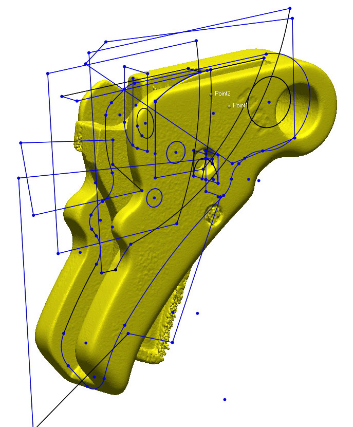

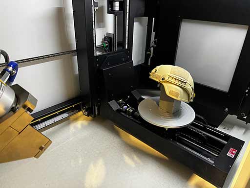
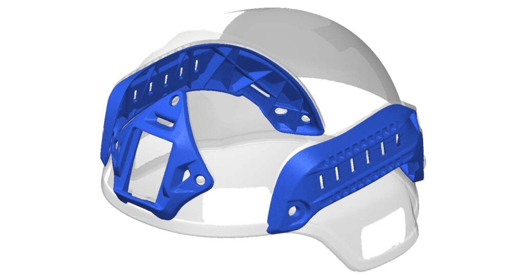

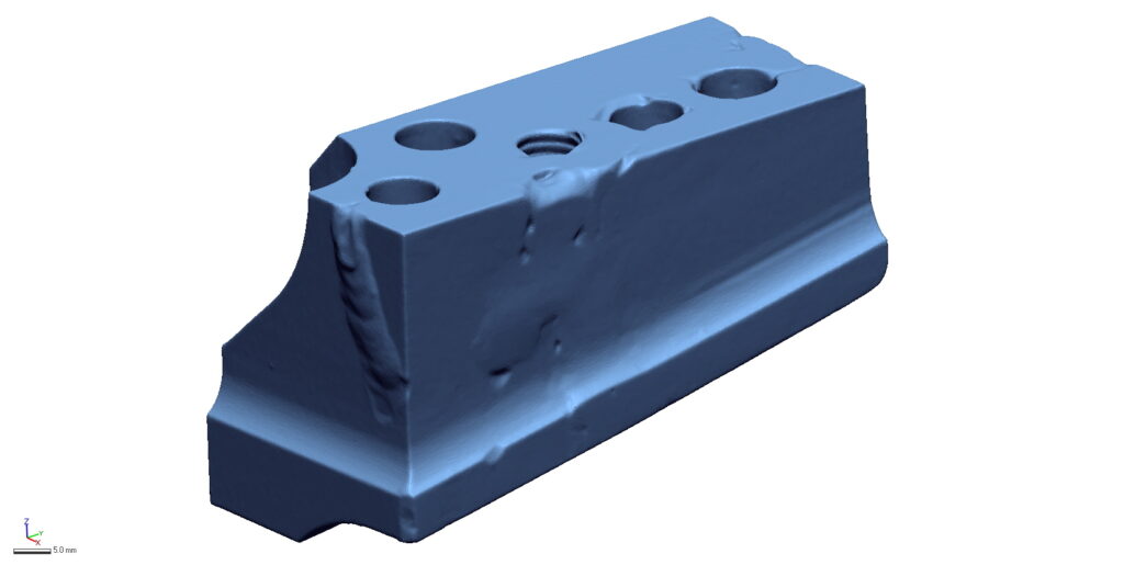
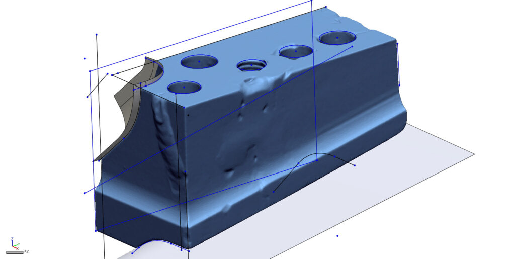


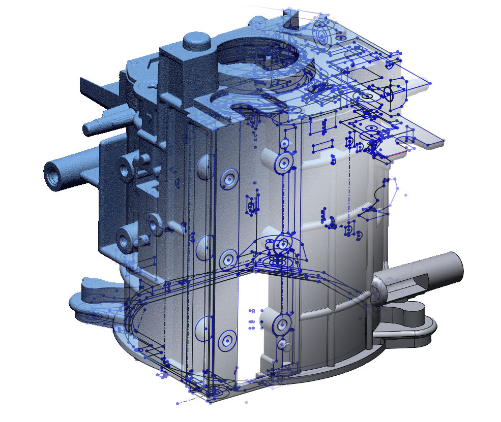
3D SCAN
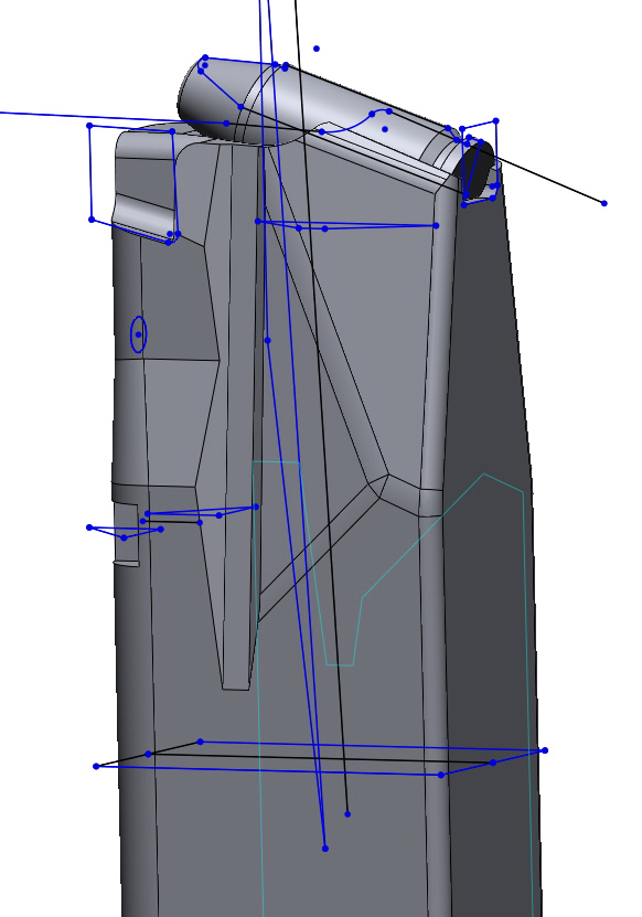
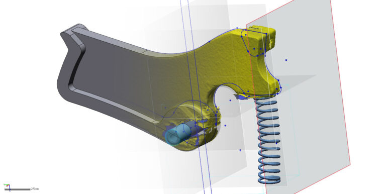
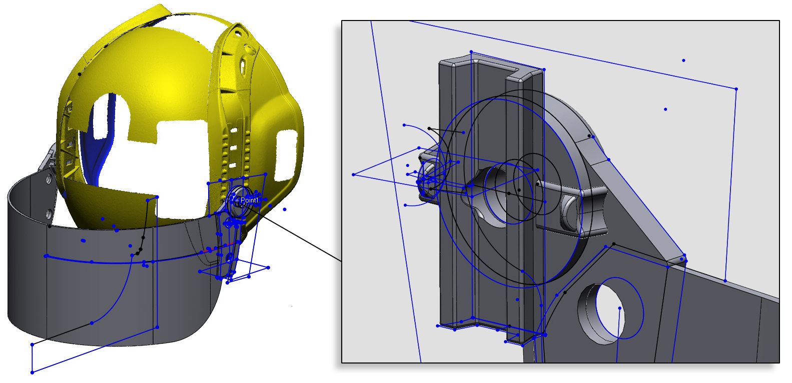
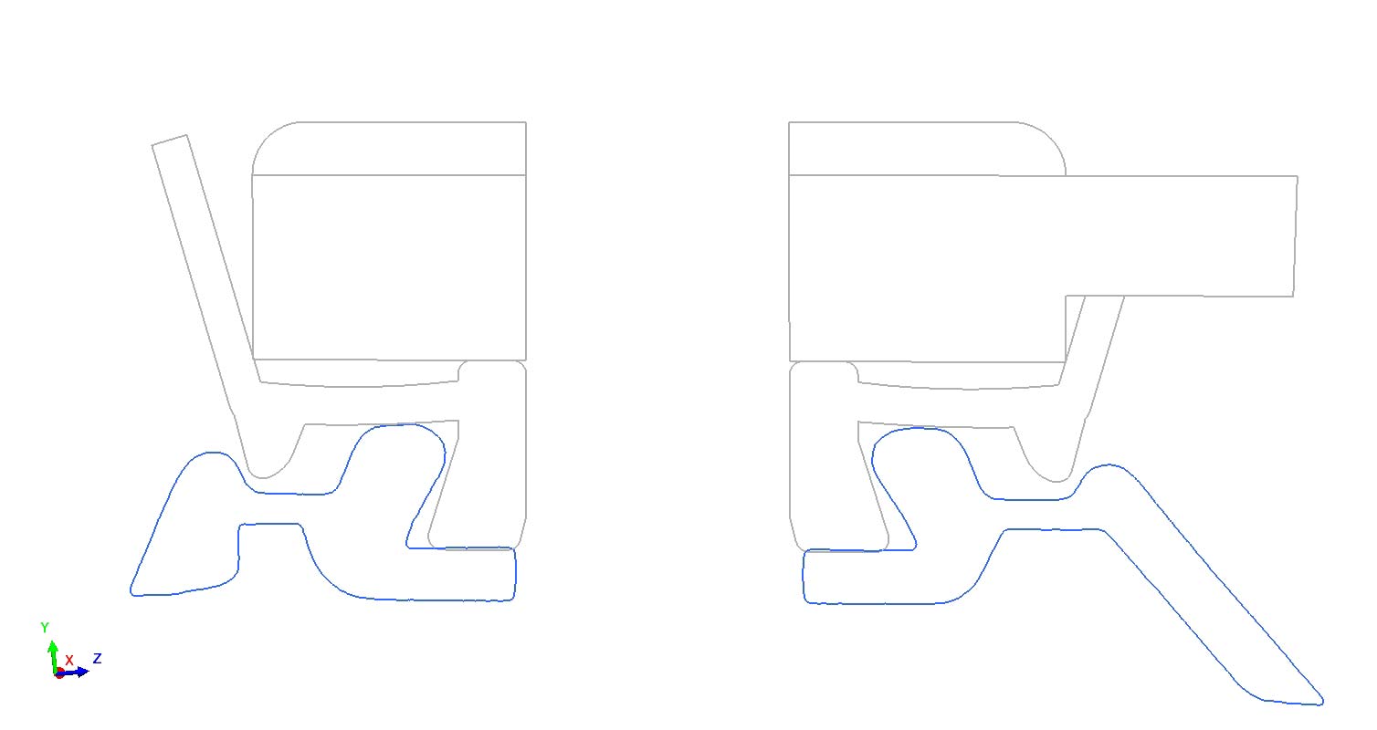
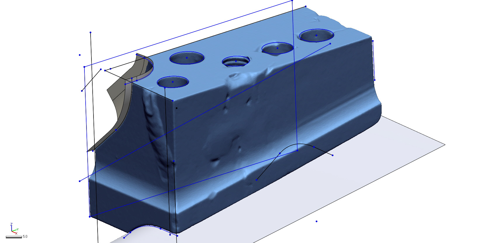
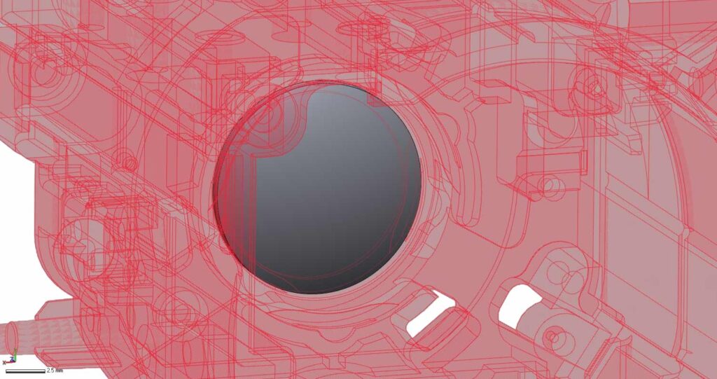
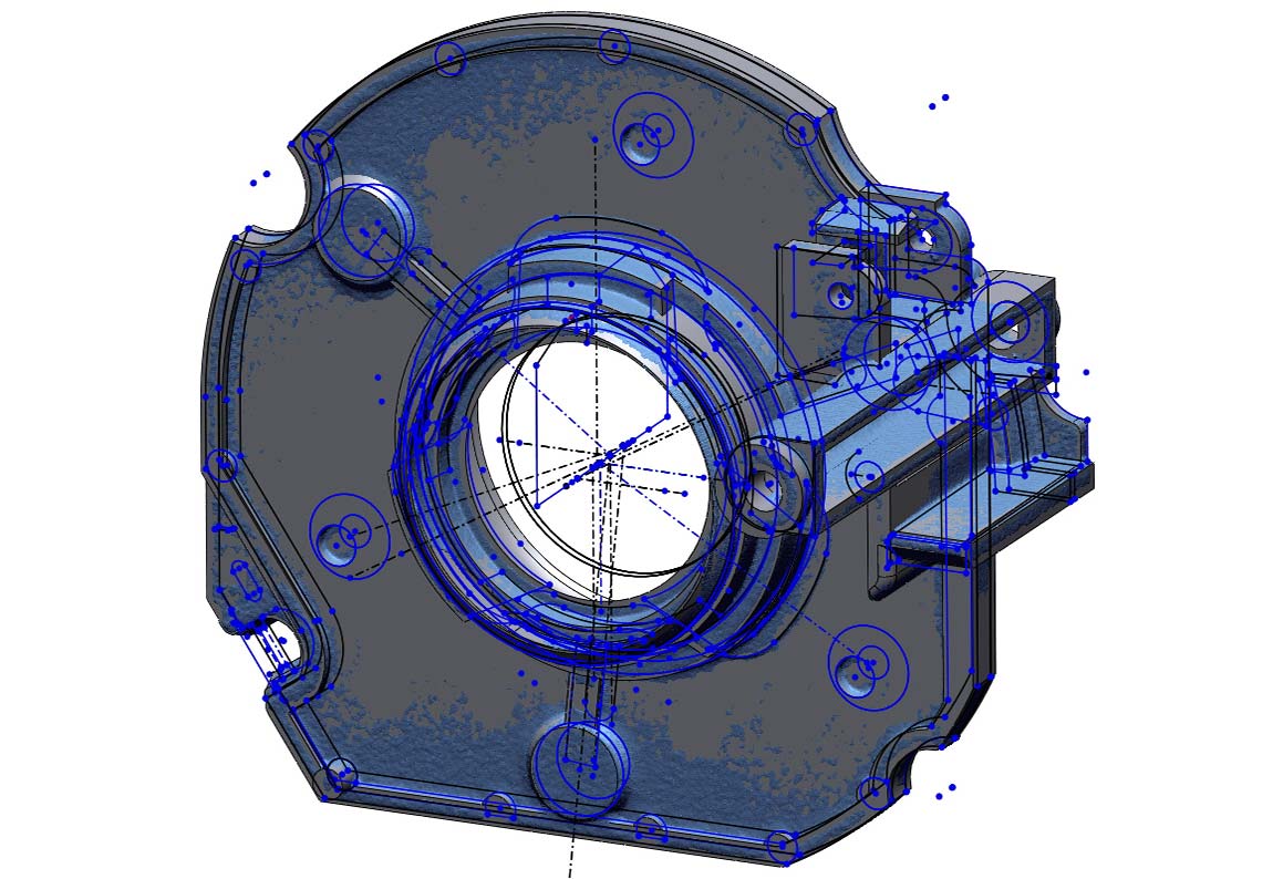
2D SKETCHES
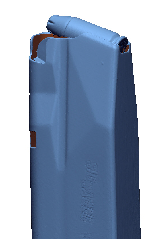
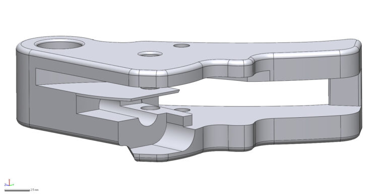
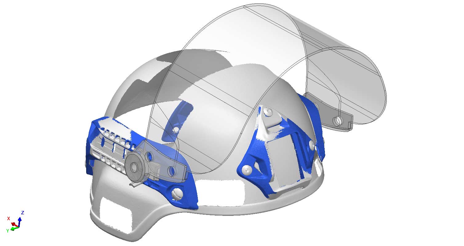
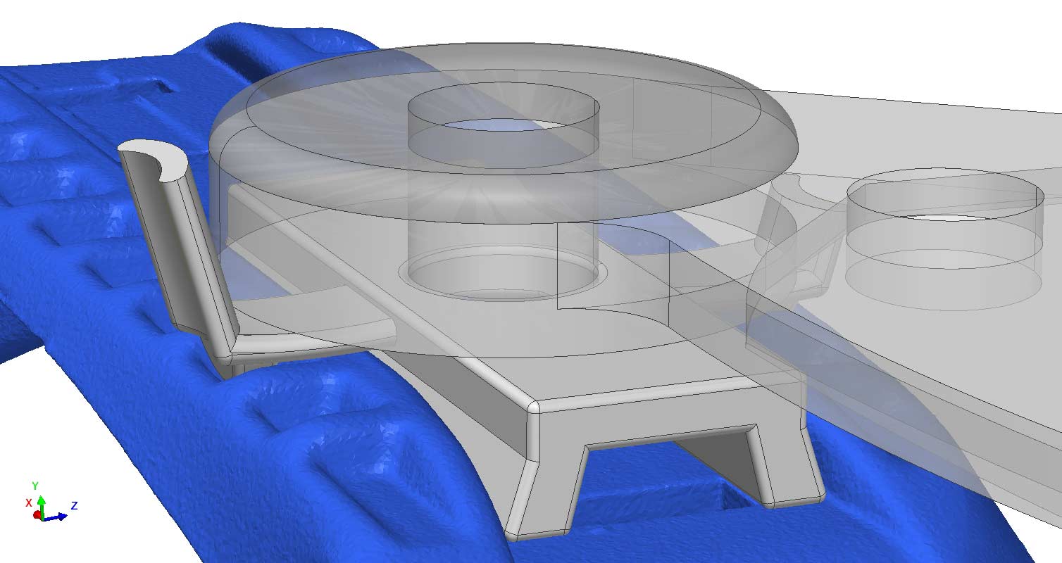
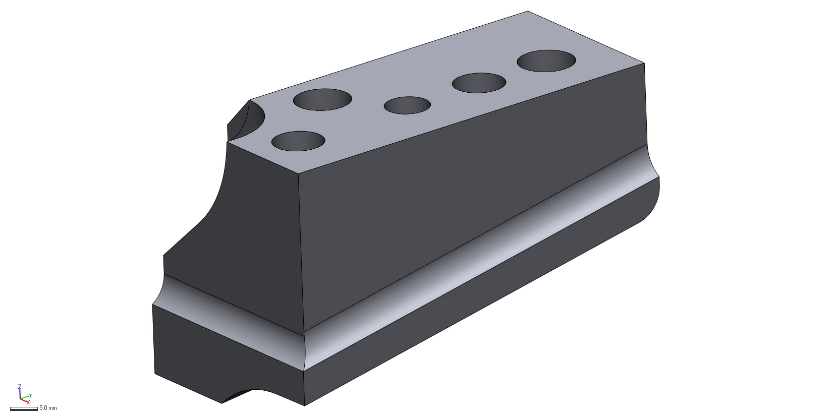
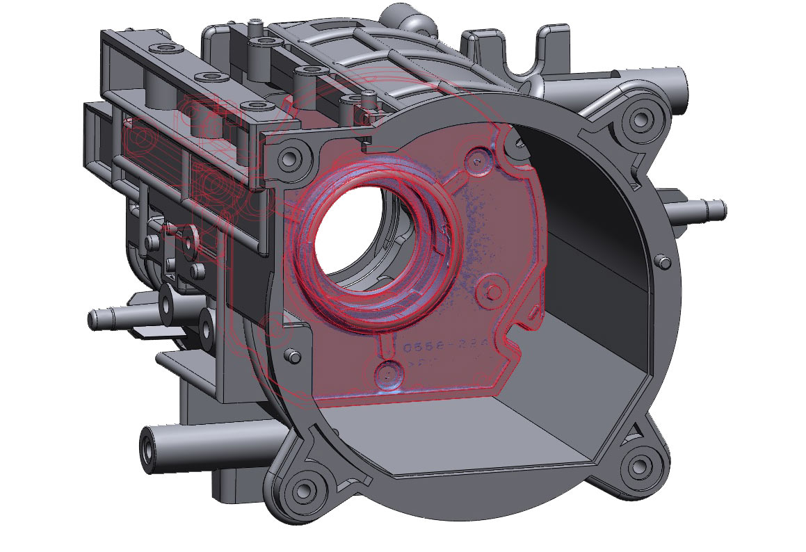
SOLID MODEL
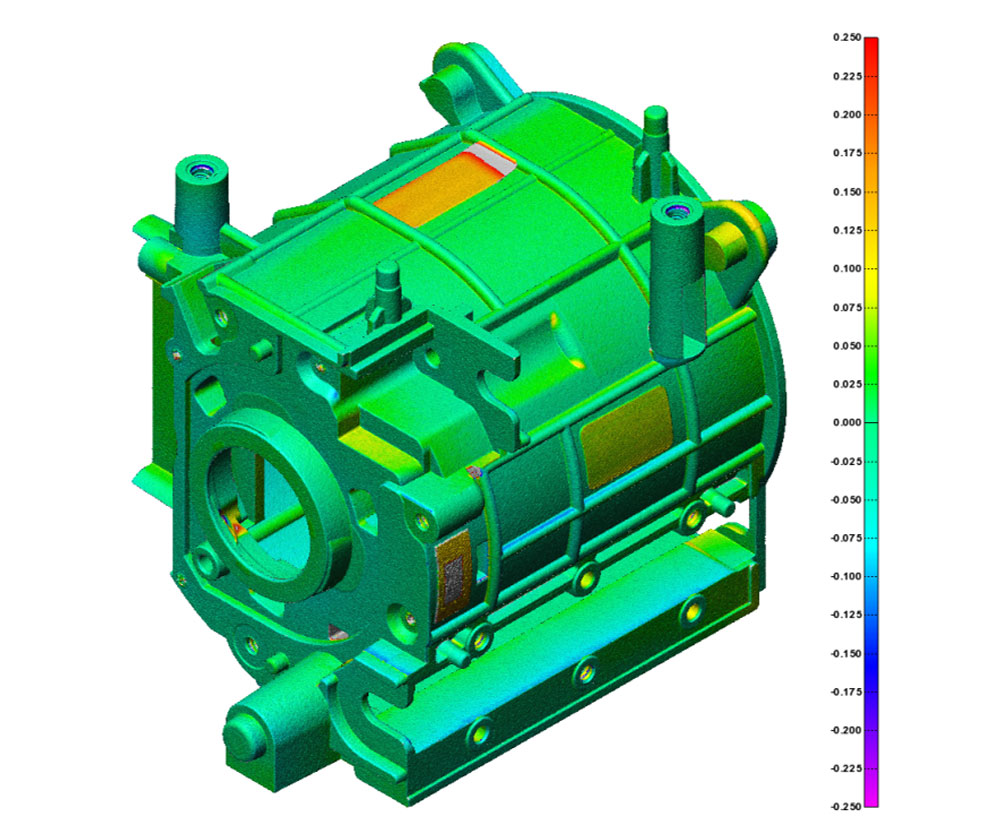

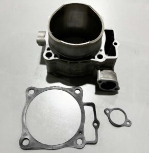
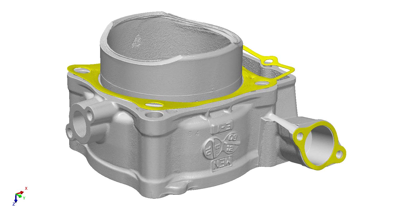
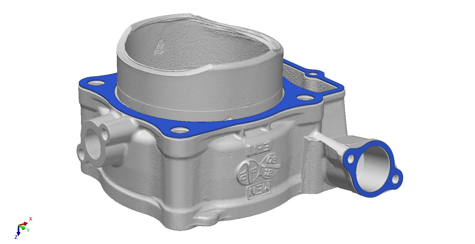
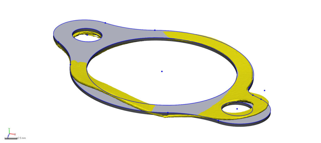
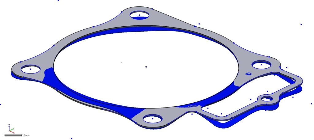


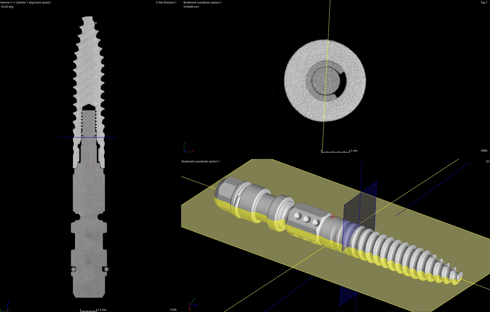
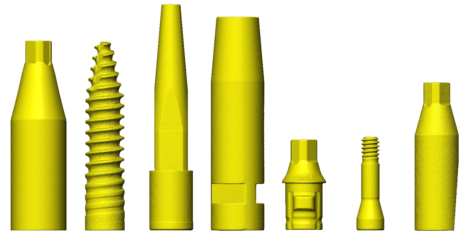
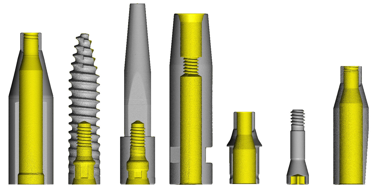


With advanced technologies we turn physical parts into digital formats including .stl & .step.
Continue reading