First Article Inspection (FAI) is a comprehensive verification process used in manufacturing to ensure that a newly produced part or component meets all specified requirements. It involves inspecting and testing the first production item against the engineering drawings, specifications, and other applicable standards.
FAI typically involves detailed inspections, measurements, and testing to verify critical dimensions, material properties, functionality, and performance characteristics of the part.
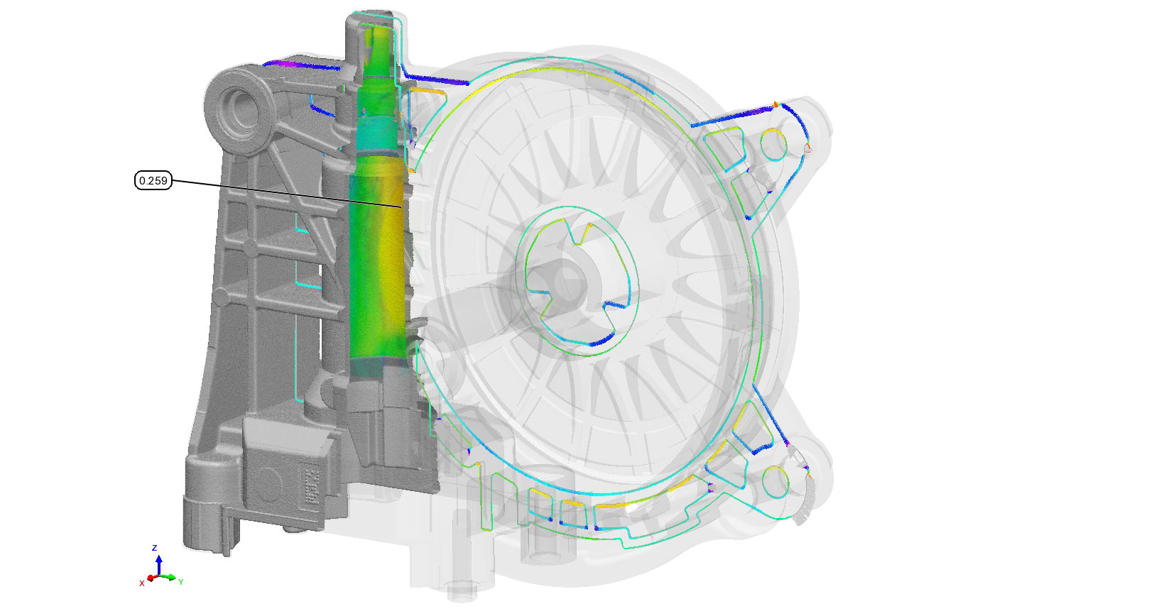
3D PROFILING
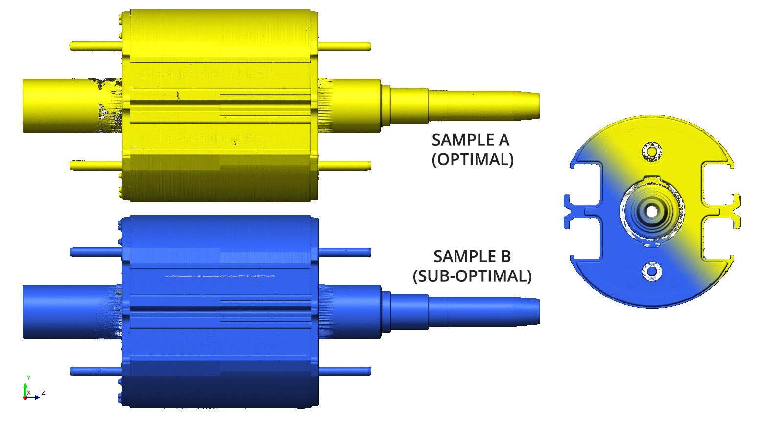
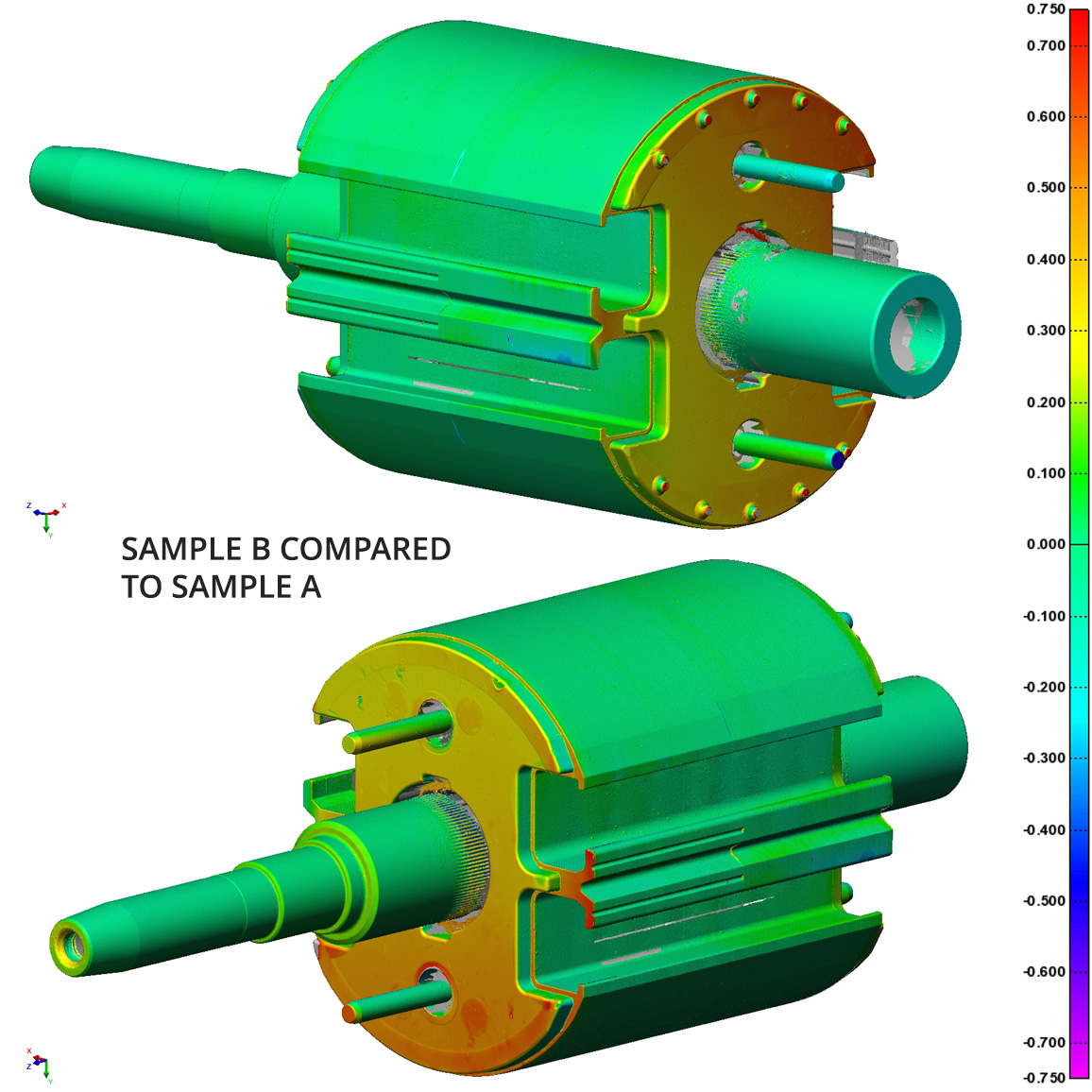
3D scanning is the process of creating a three-dimensional representation of an object. This representation is in the form of a scan file which can be compared to the perfect design model. The profile comparison heat map allows inspectors and manufacturers to identify defects, deviations, or areas of concern. The scale can be set to any tolerance:
Green to Red represents material “above” CAD surfaces
Green to Blue represents material “below” CAD surfaces
Gray represents geometry outside of the tolerance band
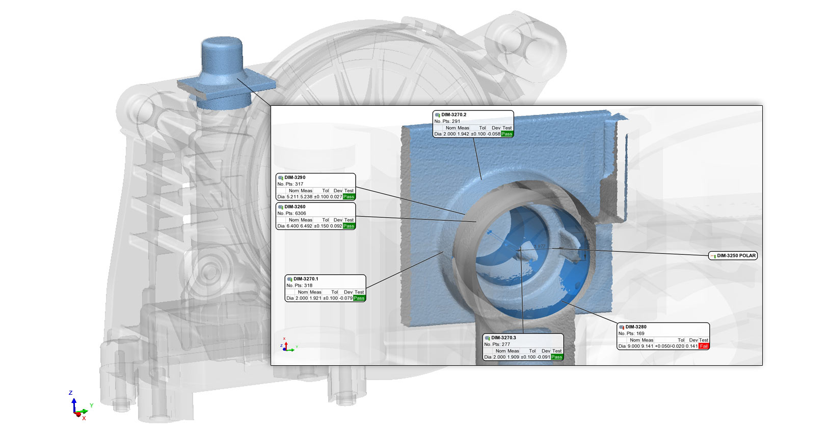
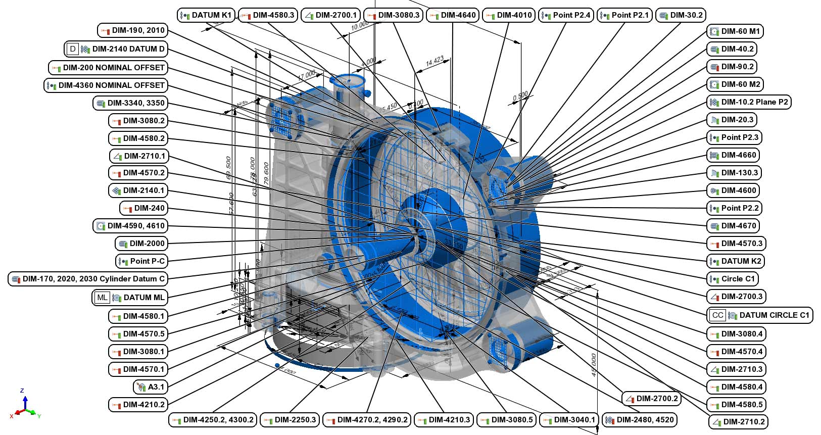
DIMENSIONAL INSPECTION
Dimensional inspection involves measuring various dimensions, such as distances, diameters, angles, complex GD&T like true positions, concentricity, and runout. These controls are used to ensure products conform to the design specifications and tolerances provided by engineering drawings.
We use PolyWorks Metrology Suite for programming, automated inspection, SPC evaluation, and imaging.
High resolution scan data acquired by our laser and CT systems is used to reverse engineer firearm components. This data can be used to modify existing hardware or build new components around historical or existing hardware.
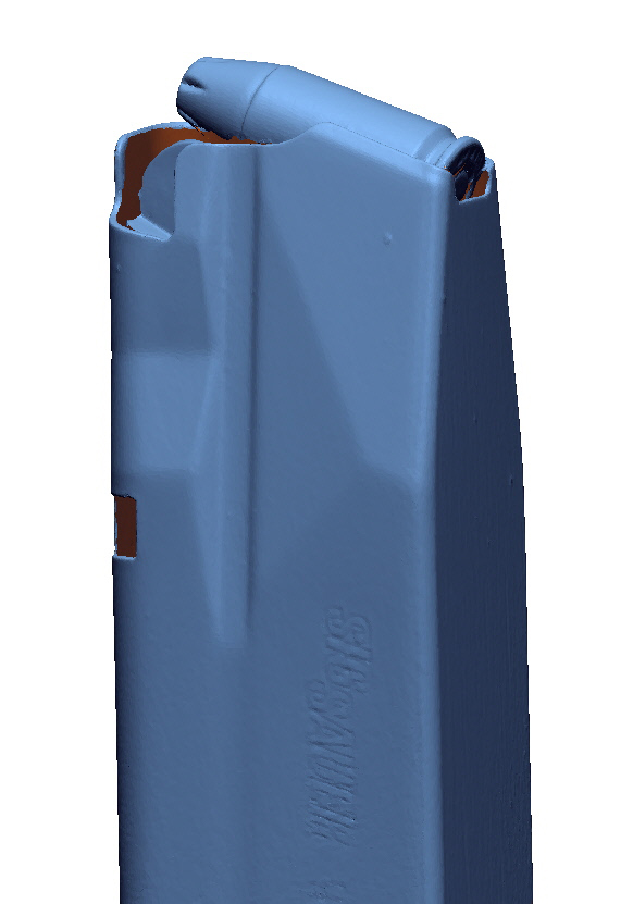
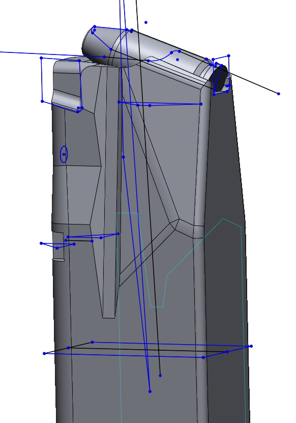
Below is a magazine that was scanned with a 9mm round. The steps include:
Laser scan the components
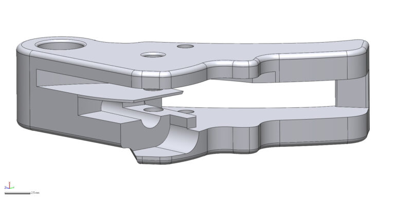
Model the components in Geomagic relative to the laser scan
Compare the produced model back to the scan file to ensure accuracy
CT SCANNING INTRICATE COMPONENTS
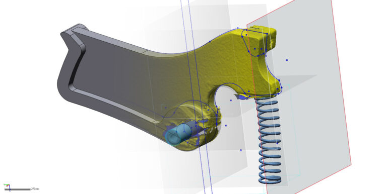
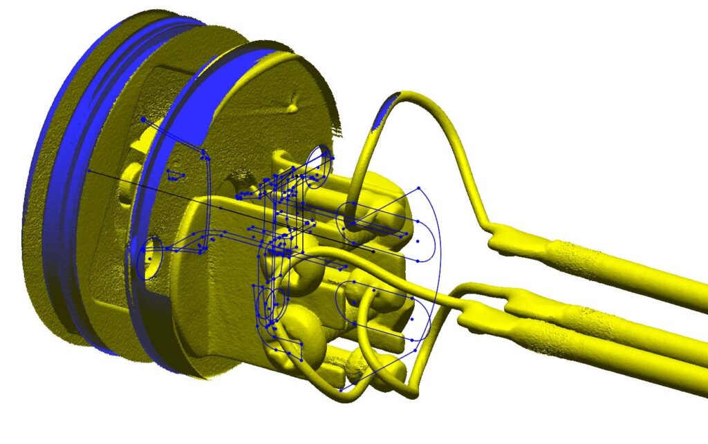
Many gun components are small and intricate. Some scanning devices may not have the resolution or ability to capture all the necessary geometry for an accurate model. CT scanning allows us to acquire surfaces like slots and assemblies without completely disassembling them. While mixed-material assemblies can be problematic (steel against plastic), there is typically a way to stage the part to get useful data.
This trigger assembly is plastic with metal springs and pins.
Laser & CT scanning produces high accuracy, water tight digital representations of products to be used for part to part and part to CAD dimensional inspection.
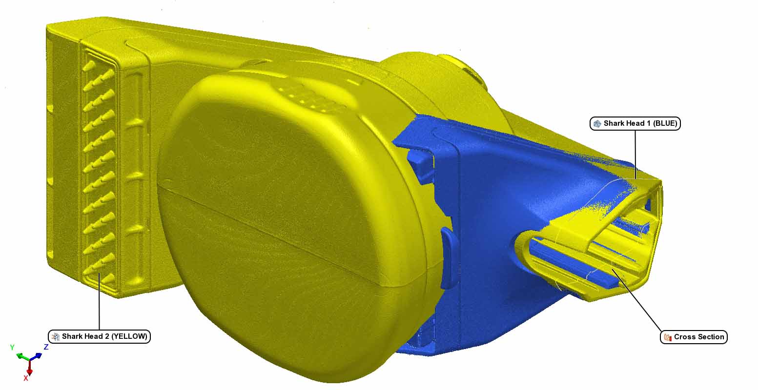
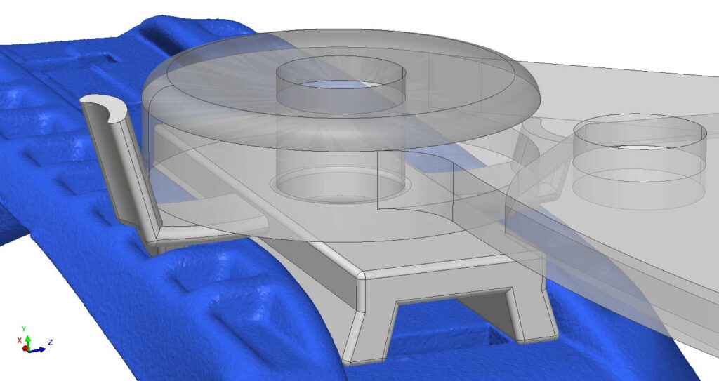
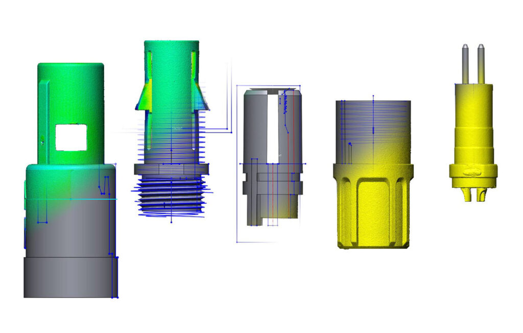
This case study demonstrates the measurement of slop between two wet vacuum attachments. One attachment was noticeably looser than the other but defining exactly where would not be possible without mapping the entire mating point.
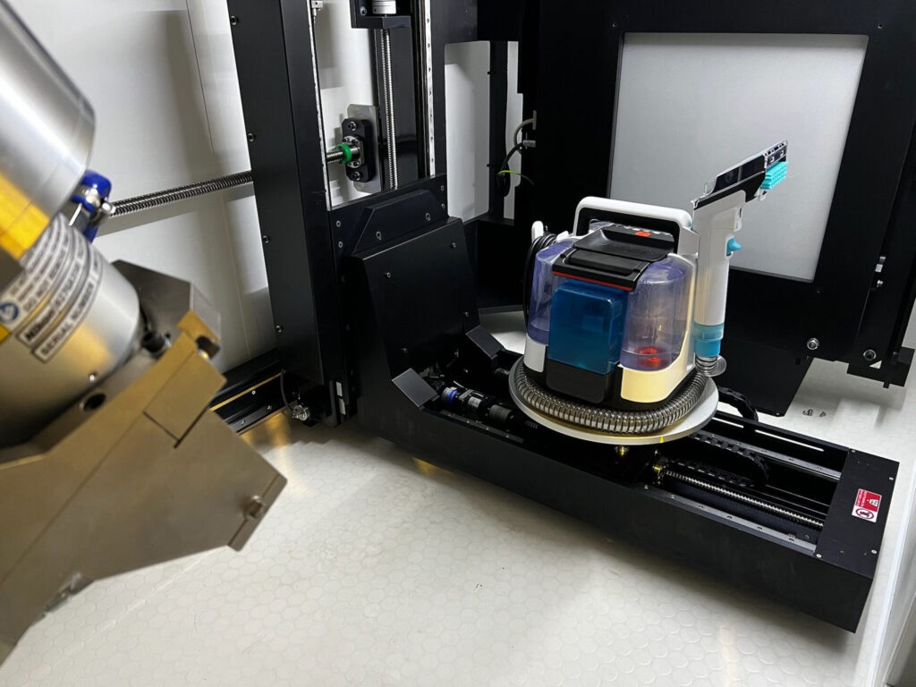
Data was acquired in our Nikon Industrial CT Scanner, exported to .STL, and imported into PolyWorks Metrology Suite for dimensional comparison.
HEAD 2 ALIGNED TO HEAD 1
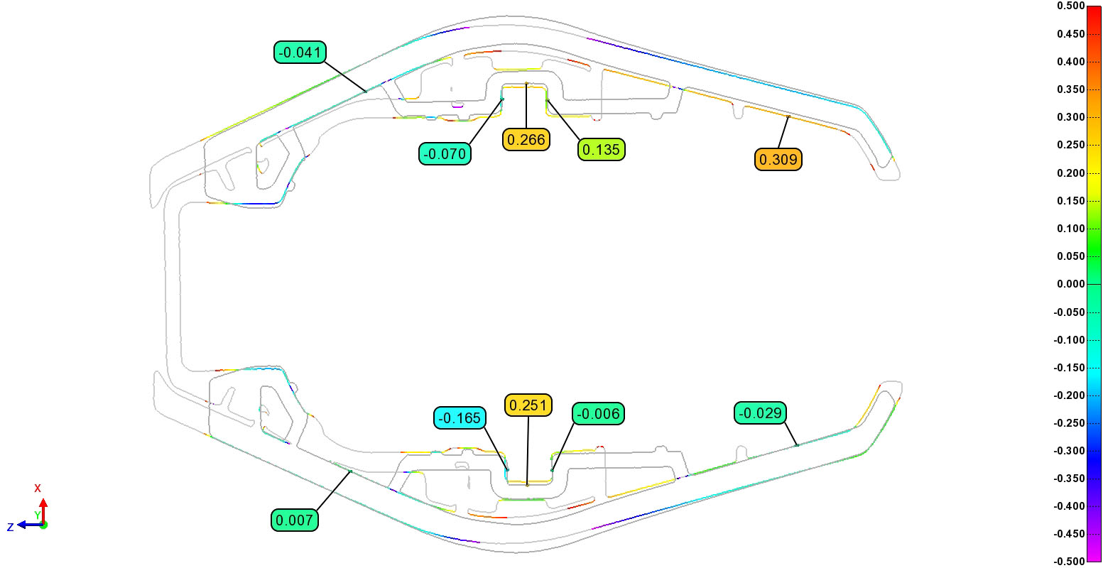
A local best fit of the mating zones was created and a cross section was placed at the area of interest: the plunger and rib track which aligns the head to the hose.
HEAD 2 ALIGNED TO HEAD 1
The 2D cross section provides a color-coded profile of a line heatmap. Green to Red colors indicate the “compared” geometry is positive (proud) compared to the reference geometry, while Green to Purple colors indicated geometry is negative (shy) compared to the reference geometry. This tells us the loose fitting head has a larger profile than the tight head and can help engineers tune their molding process.
Unlocking Innovation: The Power of 3D Scanning for Reverse Engineering
Innovation is the lifeblood of progress, driving industries forward by leaps and bounds. But what happens when innovation meets the physical world, where existing objects and components stand as formidable barriers to progress? Enter 3D scanning for reverse engineering – a transformative technology that bridges the gap between the physical and digital realms, unlocking a world of possibilities for designers, engineers, and innovators alike.
The Essence of Reverse Engineering
Reverse engineering is the process of deconstructing and understanding the design of a physical object to recreate it digitally. Traditionally, this involved meticulous measurements, manual drawings, and countless hours of labor. However, the advent of 3D scanning has revolutionized this practice, offering a faster, more accurate, and incredibly versatile solution.
Harnessing the Power of 3D Scanning
At the heart of reverse engineering lies 3D scanning technology, which enables the precise capture of an object’s geometry in stunning detail. Using techniques such as laser scanning, structured light scanning, or CT scanning, 3D scanners generate point clouds or mesh models that faithfully replicate the physical form of the object.
REVERSE ENGINEERING WORKFLOW
1. Data Acquisition: The object of interest is scanned using a 3D scanner, which captures its shape, dimensions, and surface topology.
2. Data Processing: The raw scan data is processed to remove noise, align multiple scans (if necessary), and create a clean, detailed representation of the object’s geometry.
3. Model Creation: From the processed scan data, a digital model is generated using specialized software. This model faithfully replicates the physical object, serving as a blueprint for further design and analysis.
4. Design Enhancement: With the digital model at hand, designers and engineers can refine, modify, or optimize the object’s design to meet specific requirements or improve its performance.
5. Validation and Analysis: The digital model undergoes rigorous testing and analysis to ensure its accuracy and functionality. CAD comparison reports are used to verify dimensional accuracy whil finite element analysis (FEA), simulation, and other techniques help validate the design and identify areas for improvement.
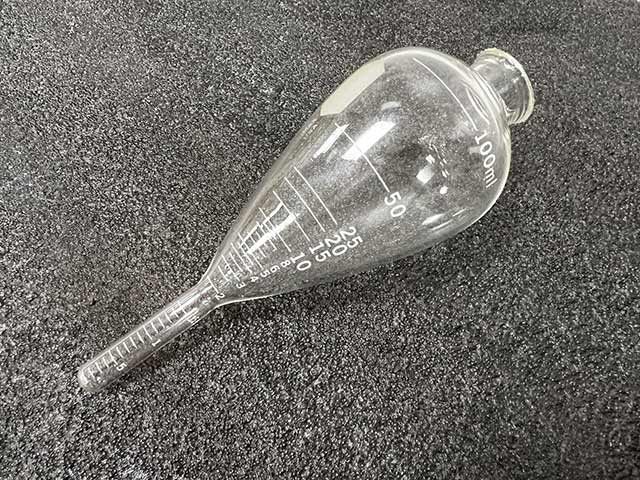
MEASURING TEST TUBES & VIALS FOR WALL THICKNESS AND VOLUME
CT scanning plays a pivotal role in assessing the wall thickness and volume of glass components, offering critical insights for manufacturing processes and product quality. Glass, known for its brittleness and susceptibility to defects, requires meticulous inspection to ensure structural integrity and performance. CT scanning provides a non-destructive means of examining these components, offering precise measurements of wall thickness and volume with unparalleled accuracy. By detecting variations in thickness and identifying potential flaws, CT scanning enables manufacturers to optimize production processes, enhance product reliability, and uphold stringent safety standards. The comprehensive evaluation provided by CT scanning ensures that glass components meet the highest quality requirements, ultimately contributing to safer and more durable end products.
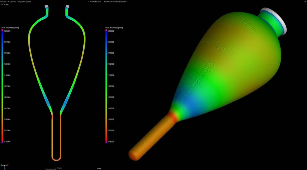
CT SCANNING TO MEASURE WALL THICKNESS
CT scanning is used for evaluating wall thickness in a wide range of materials and structures. By utilizing X-ray technology to penetrate objects, CT scanning generates detailed 3D images that allow for precise measurements of wall thickness. This non-destructive technique is invaluable for industries such as manufacturing, aerospace, and automotive, where ensuring structural integrity is paramount. This image demonstrates a total mapping of the thickness of the tube with variable results from .75mm to 2.55mm.
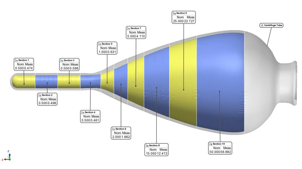
VOLUME OF GRADUATION MARKS
CT scanning offers a precise and non-destructive method for measuring volume in objects with complex geometries. We were able to segment, virtually cap, and extract volumetric measurements of the tube at various graduation marks.
The nominal “as-marked” volume states 100ml and the measured volume equals 100.533ml – a deviation of just 0.5% of the volume. However, sub-sections like section 5 have a deviation of 27%.
In the dynamic landscape of modern manufacturing, precision is paramount. Enter 3D scanning – a transformative technology reshaping the way industries approach quality control, reverse engineering, and dimensional inspection. At its core, industrial 3D scanning utilizes advanced data capture techniques to produce detailed, three-dimensional representations of physical objects with unprecedented accuracy. But what exactly is industrial 3D scanning for, and how is it revolutionizing the manufacturing landscape?
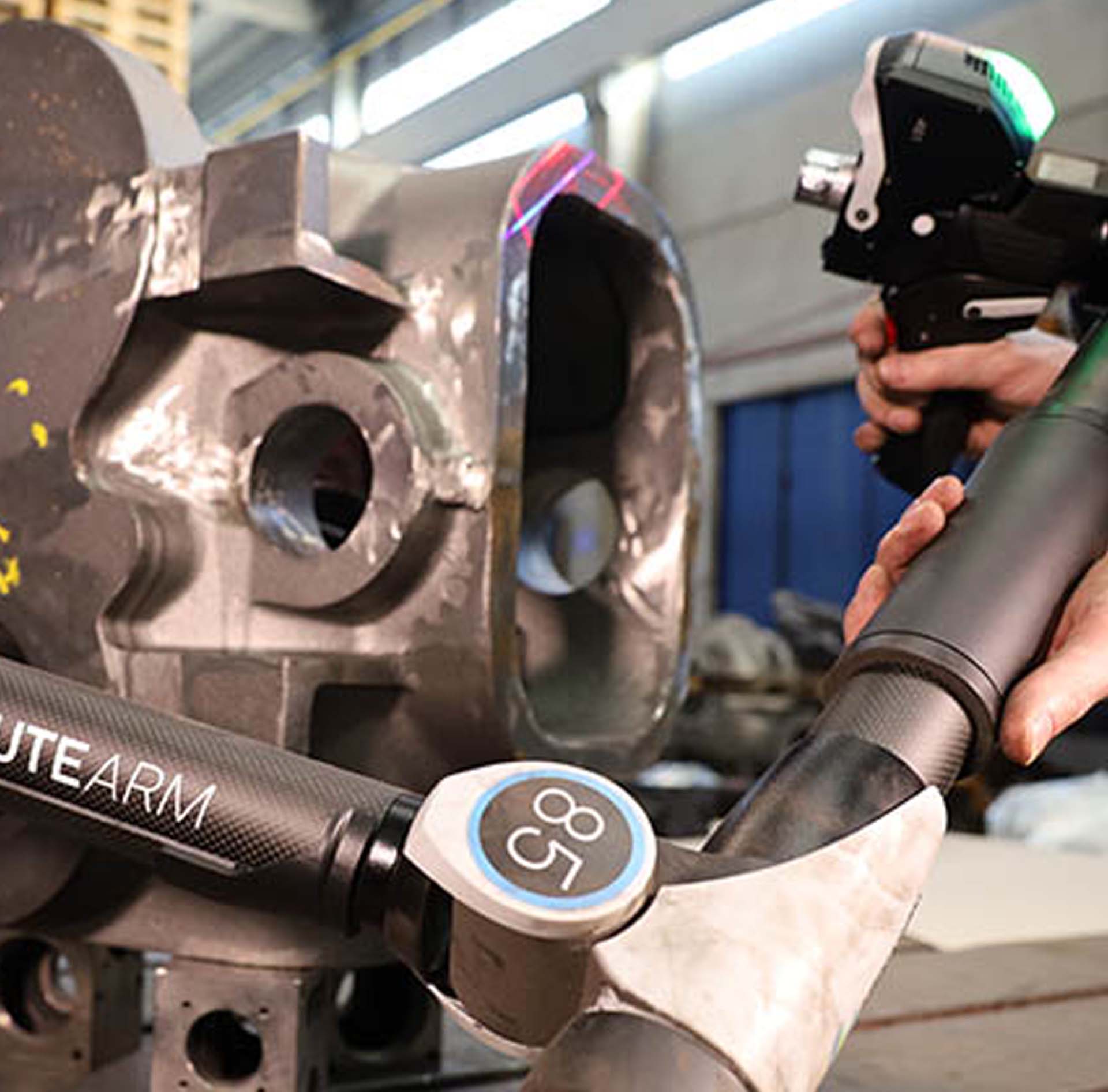
Hexagon Portable AS1 Laser Scanner
CAD COMPARISONS
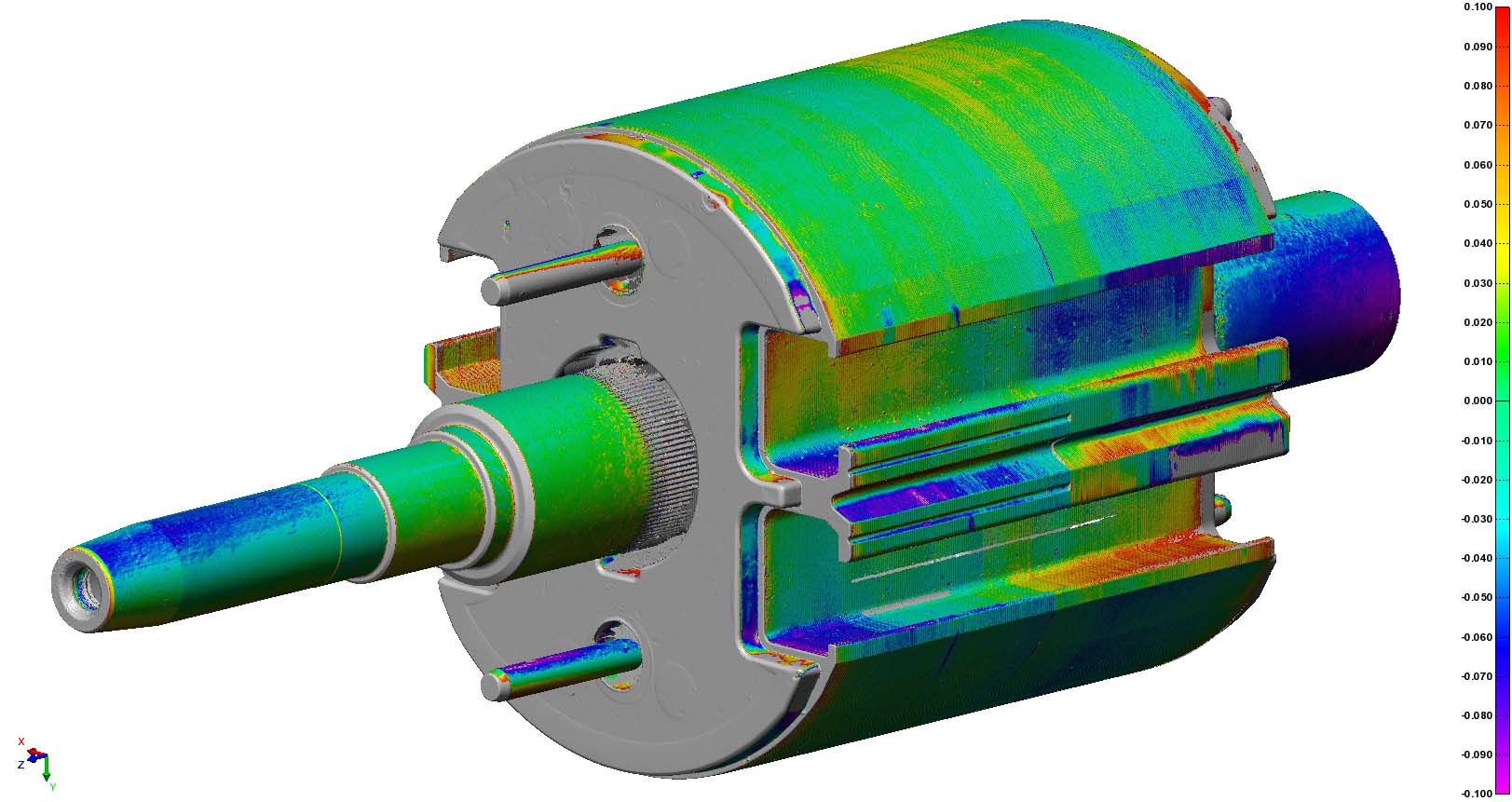
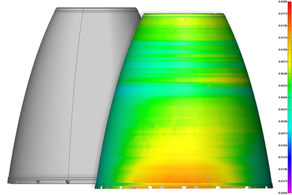
In manufacturing, ensuring product quality is non-negotiable. Industrial 3D scanning plays a pivotal role in this endeavor by providing manufacturers with the means to meticulously inspect entire components and assemblies for defects, deviations, and inconsistencies. From intricate aerospace parts to automotive components, 3D scanning offers a comprehensive solution for identifying imperfections early in the production process, minimizing waste, and optimizing product performance.
Scan to CAD Deviation Map of Engine Nozzle
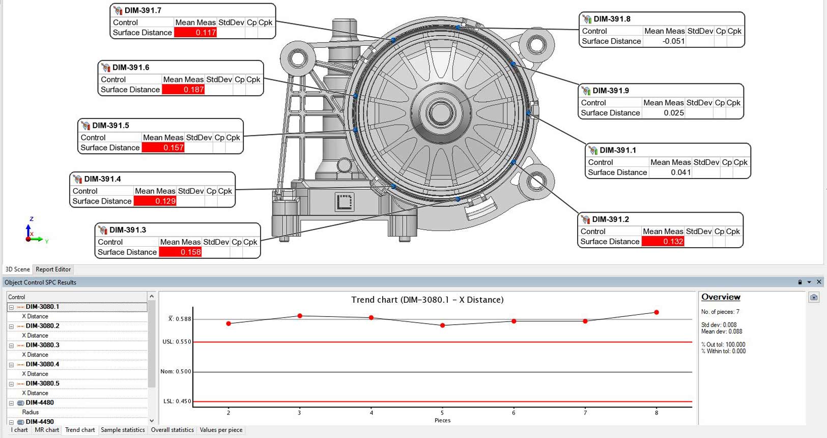
DIMENSIONAL INSPECTION
Precision is the hallmark of quality, and dimensional accuracy is a critical aspect of manufacturing excellence. Industrial 3D scanning provides manufacturers with a reliable method for verifying the dimensional integrity of components and assemblies, ensuring they meet tight tolerances and specifications. By comparing scanned data to CAD models or reference standards, manufacturers can confidently validate the accuracy of their products, safeguarding against costly errors and rework.
SPC Charts & Dimesional Results in PolyWorks Software
REVERSE ENGINEERING
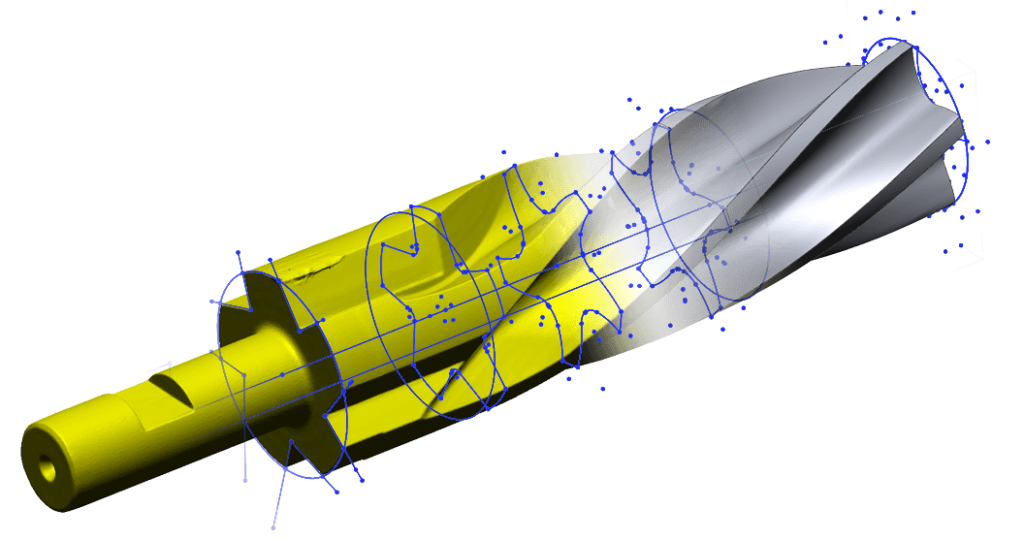
The ability to replicate and improve upon existing designs is a cornerstone of innovation. Industrial 3D scanning facilitates this process by capturing the exact geometry of physical objects, allowing engineers to create digital models that can be modified, optimized, or reproduced as needed. Whether it’s redesigning legacy components or enhancing product functionality, 3D scanning enables manufacturers to unleash their creativity and drive continuous improvement.
Scan to Geometric CAD Models using Geomagic Design X Software
In conclusion, industrial 3D scanning is a versatile and indispensable tool that empowers manufacturers to achieve new levels of precision, efficiency, and innovation. Whether it’s enhancing product quality, accelerating design iterations, or ensuring dimensional accuracy, 3D scanning is reshaping the manufacturing landscape and driving advancements across industries. As technology continues to evolve, the potential of industrial 3D scanning to unlock new possibilities and propel us towards a future of manufacturing excellence is boundless.
FAILURE INVESTIGATION OF HUMAN SUPPORT SYSTEM (CHAIR)
Have you fallen and can’t get up?
Are you struggling to return something to Amazon?
Are you tired of finding 3500mm cubed voids in your products?
Do you wonder why everything is more expensive but doesn’t last as long?
Us too.
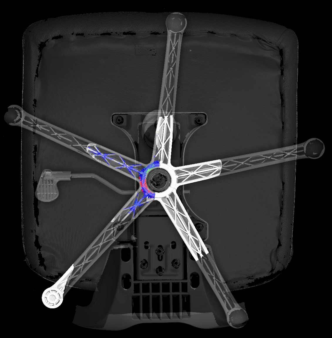
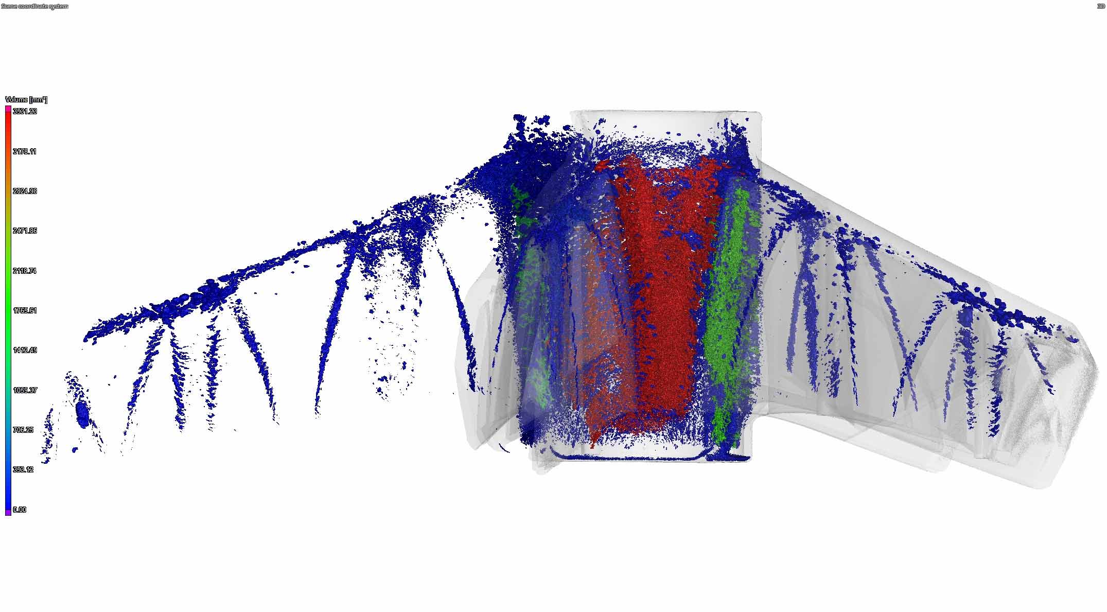
This case study explores the failure of a human support system (chair.)
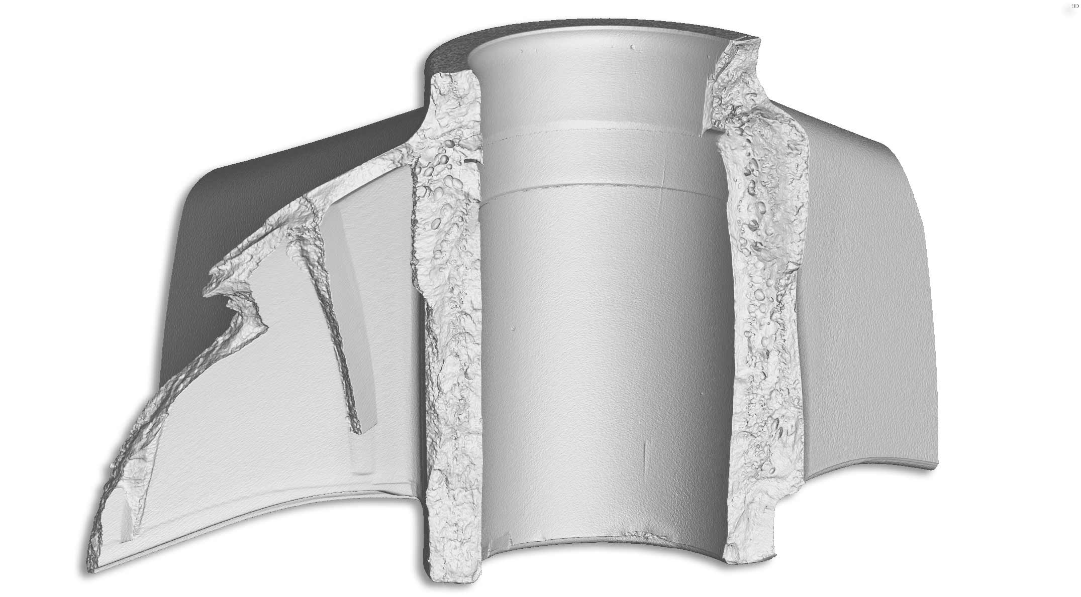
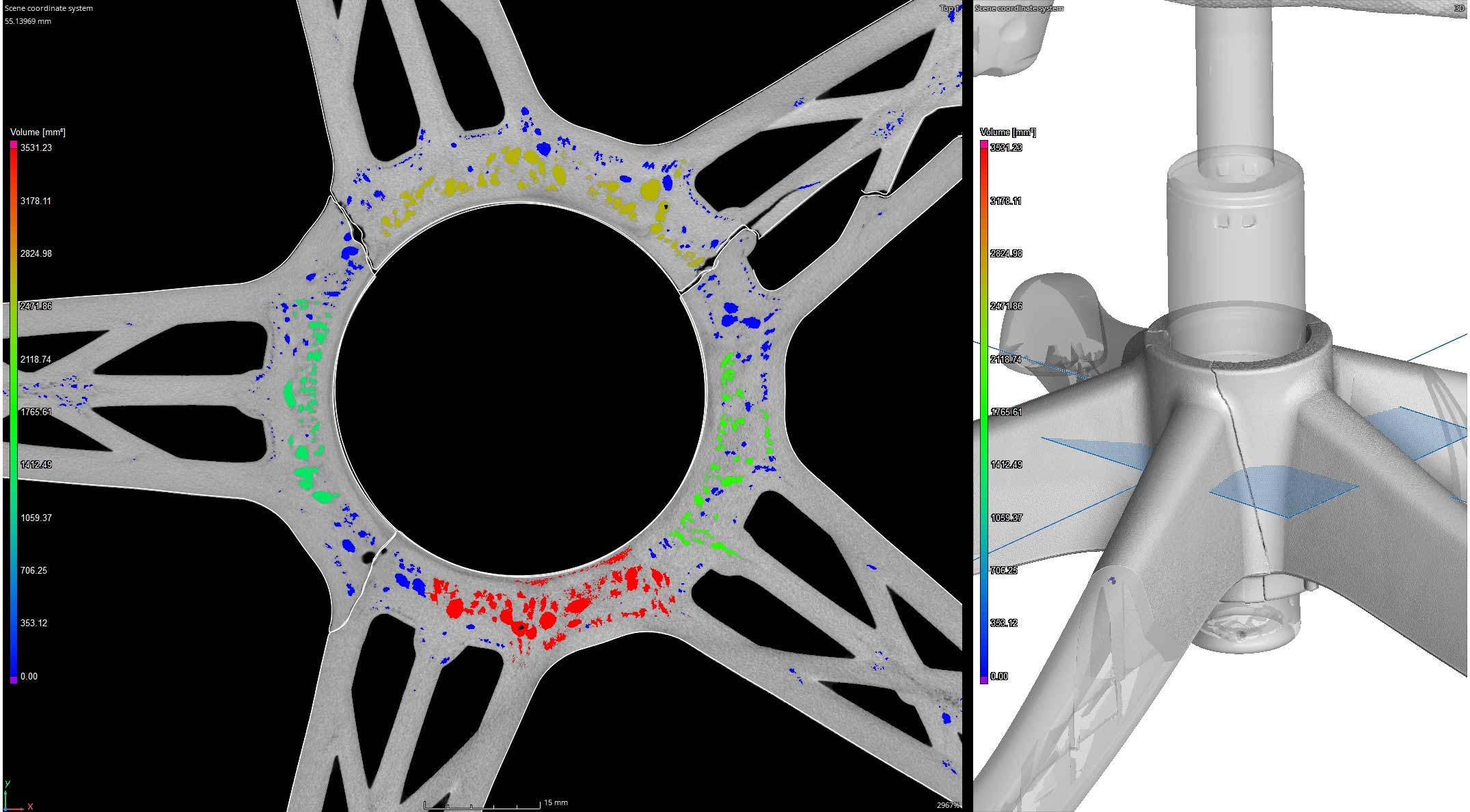
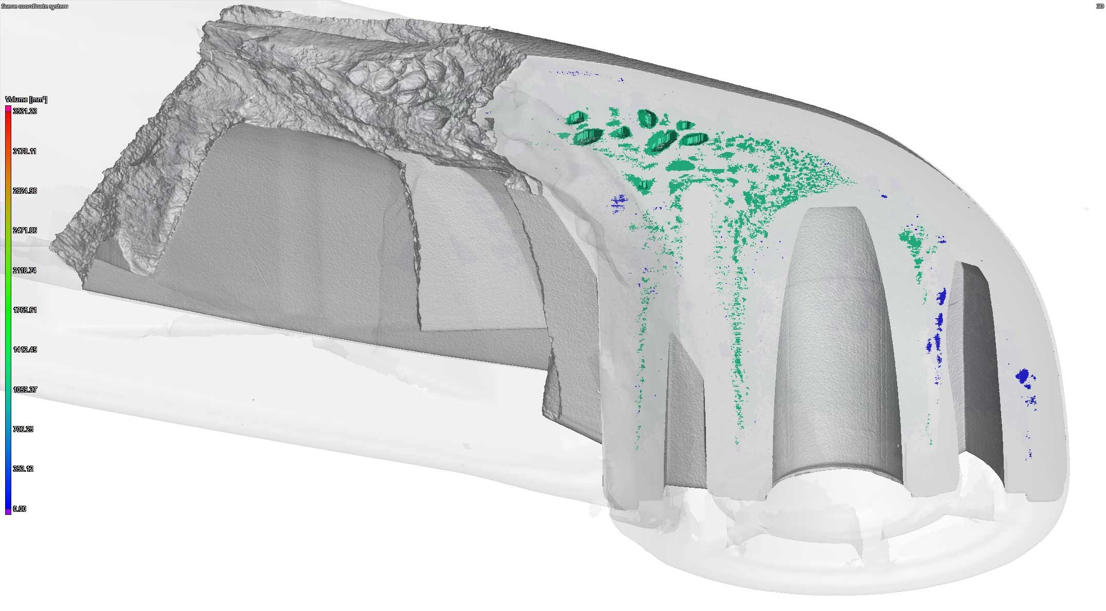
Industrial CT Scanning is a powerful non-destructive imaging technique used to inspect the internal structure of objects. When applied to plastics to detect porosity, CT scanning provides detailed cross-sectional and 3D rendered images revealing the distribution, size, and shape of voids or pores within the material.
Everyone from manufacturers to law firms have used our services to assist with their fact finding, point of origin, or root cause evaluations.
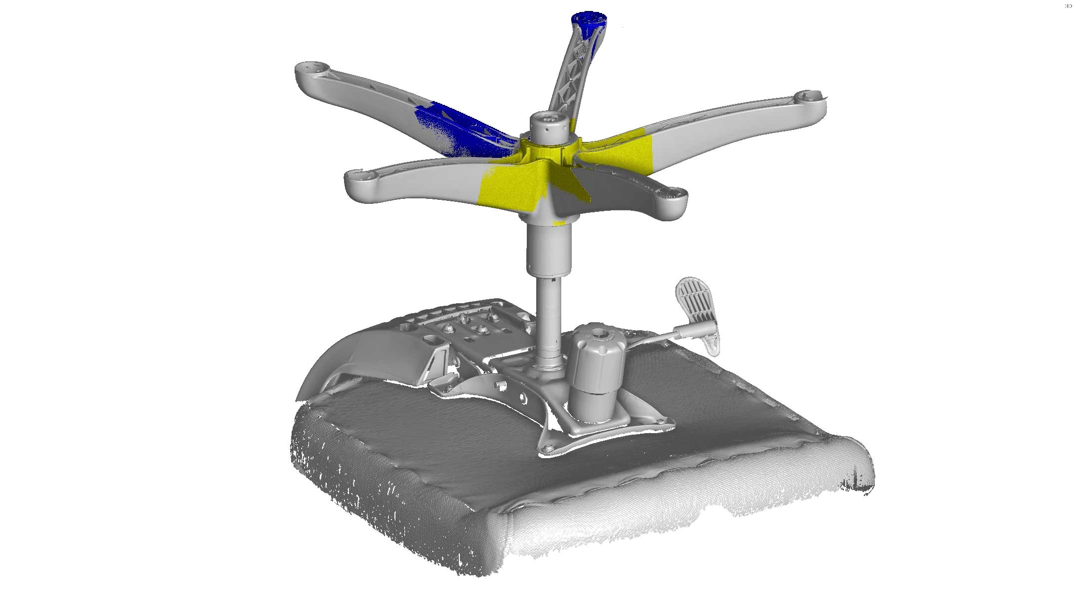
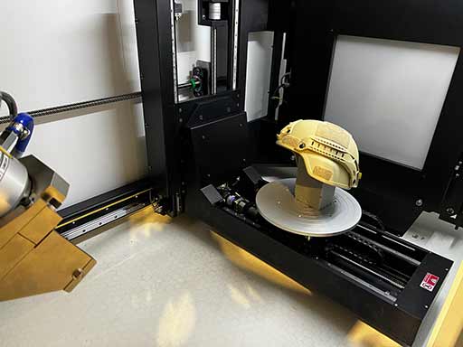
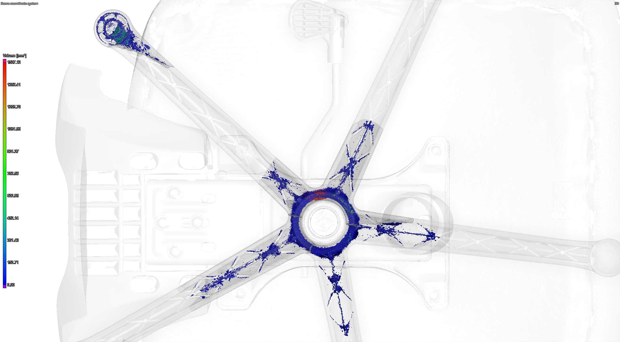
We combine many hardware and software capabilities for the best possible evaluation of products. Because of the size of the chair we used a high accuracy laser scanner (Hexagon Absolute AS1) to capture the overall geometry of a still intact chair. We then created a coordinate system and aligned additional scans of the broken pieces in PolyWorks.
Once everything was aligned properly we imported the .STL mesh files into Volume Graphics to begin aligning the individual CT scans. The CT scans were acquired using our Nikon Microfocus X-Ray & CT cabinet. After the alignments were complete we extracted the volumetric porosity to find voids and cavitation as large as 3500mm3 and found a significant concentration at the base of the chair.
DESIGNING NEW COMPONENTS FOR PERFECT FIT AND FUNCTION
Combining the power of the world’s best scanning hardware and software allows us to produce models with incredible accuracy. This case study focuses on acquiring high resolution, water tight geometry using laser and CT scanning technologies.
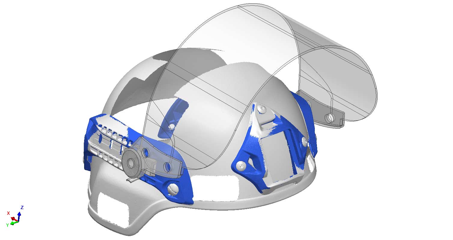
This helmet has several components with attachment features for accessories like lights, visors, and earmuffs. However, if you don’t have existing CAD, how do you effectively design new products?
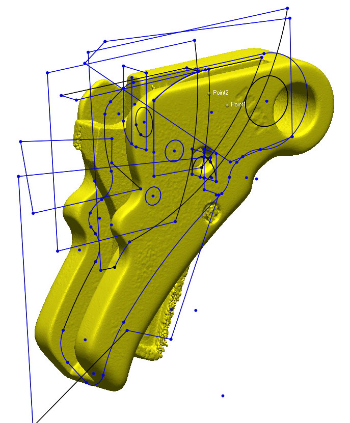
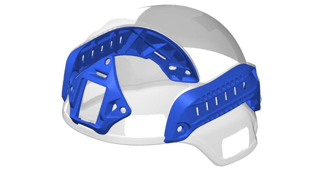
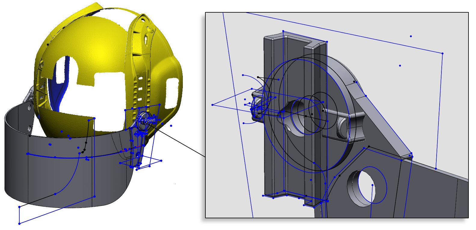
The first step is to acquire water tight, high resolution data. Water tight data means no data is missing in the file. This is important for properly designing a product around all scenarios – if data is missing, you can’t understand proper fit and function. We scanned and segmented the attachment points and built a coordinate system to begin modeling visor attachment mechanisms.
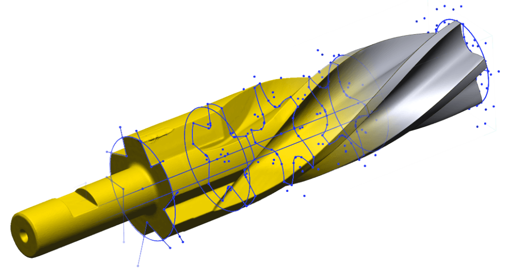
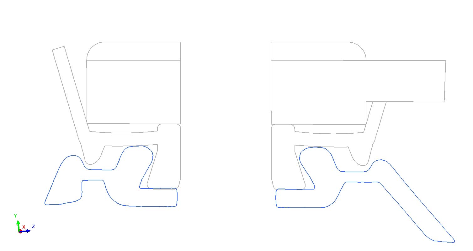
Below shows the 2D sketches produced in Geomagic.
The final step of any reverse engineering project is to verify accuracy of the produced model. This verification takes the form of either Scan to CAD profile comparisons, or visual checks with 2D cross sections. The visor slides fit inside the tracks and the clips have curved tensioners to ensure tight fits into the slots.
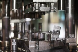
Scanning technologies are used to reverse engineer tooling die steels. Over time steel wears, breaks, or is modified to produce a better part. Design files become lost or do not match the modifications.
Using our high resolution laser pCMM we can reproduce worn die steels into toolable .step CAD models.
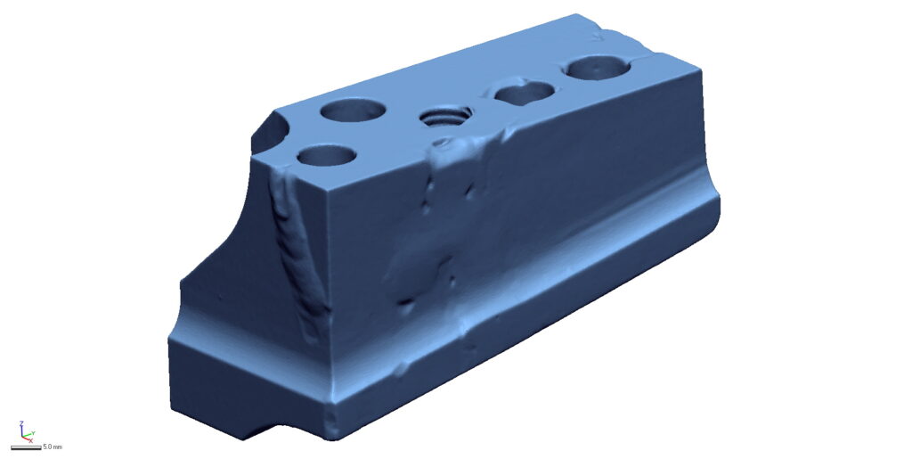
STEP 1ACQUIRE SCAN DATA
Lorem ipsum dolor sit amet, consectetur adipiscing elit. Ut elit tellus, luctus nec ullamcorper mattis, pulvinar dapibus leo.
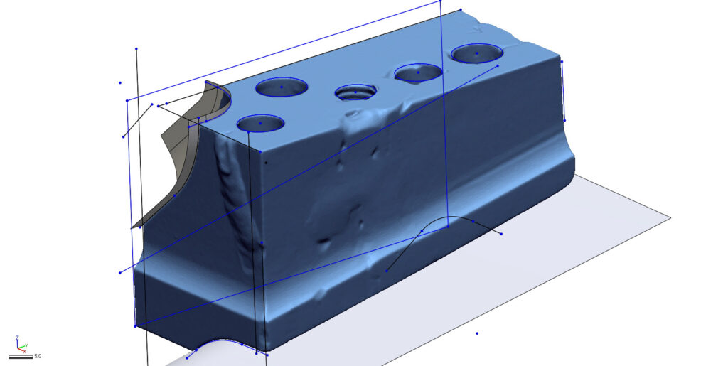
STEP 2SKETCH THE GEOMETRY
Geomagic Design X offers a large variety of modeling tools like 2D sketching, extrusions, lofting, patterning, and symmetry.
Assets are created and merged into a solid model.
STEP 3TUNE THE MODEL
After a model is created it is tuned to achieve the minimal amount of deviation. Sometimes surfaces need to be moved or hole sizes adjusted.
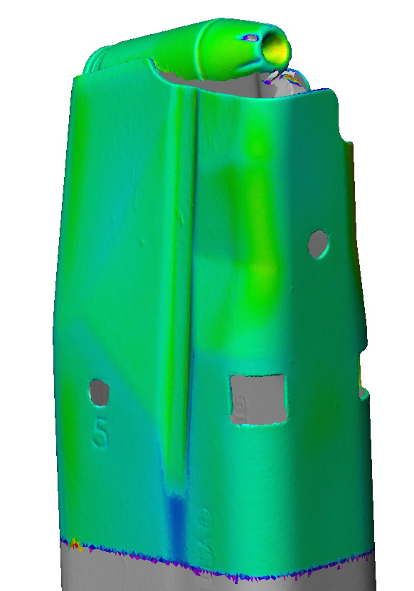
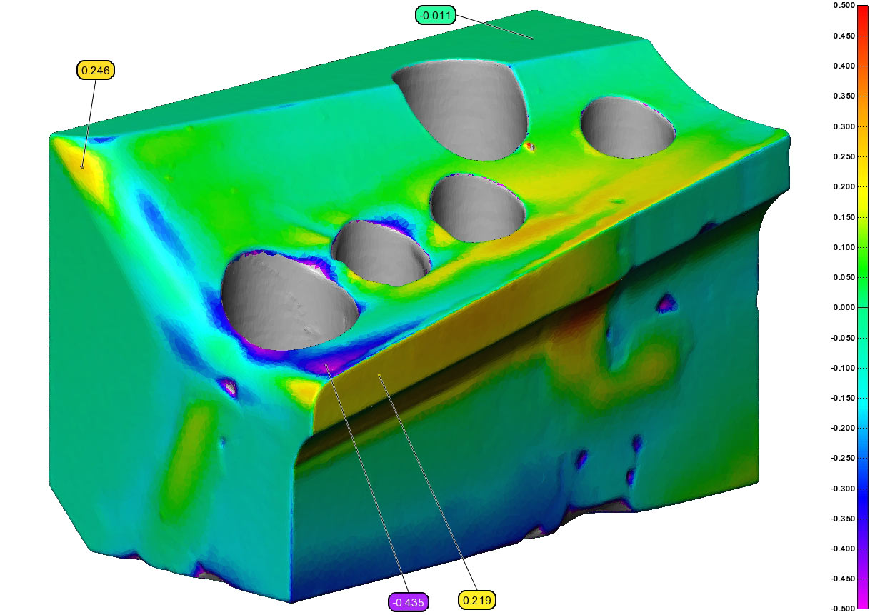
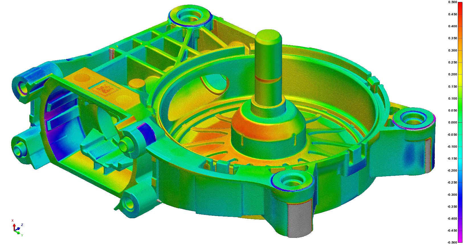
STEP 4REPORT THE DEVIATION
The deliverables for every reverse engineering project include a final .step model as well as a deviation report. This profile heat map shows the areas where the produced model differentiates from the original scan file.
Sometimes deviation is inevitable where a cracked component was stitched back together, while other times a free-form surface cannot be perfectly geometrically replicated.