Inspecting tube welds in aerospace, defense, and nuclear applications is not just important; it’s absolutely essential for ensuring safety, preventing environmental contamination, maintaining operational efficiency, complying with regulations, mitigating risks, assuring quality, and ensuring long-term performance.
Tube welds are critical components in various systems such as piping, reactors, and steam generators. Any flaws or defects in welds could compromise the structural integrity of these systems, leading to catastrophic consequences.
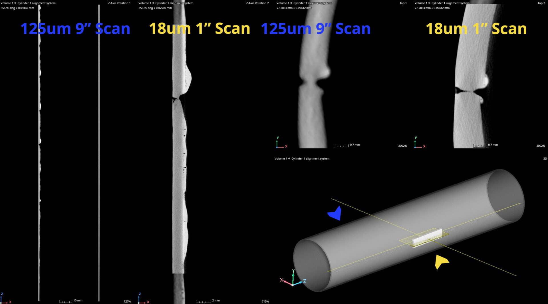
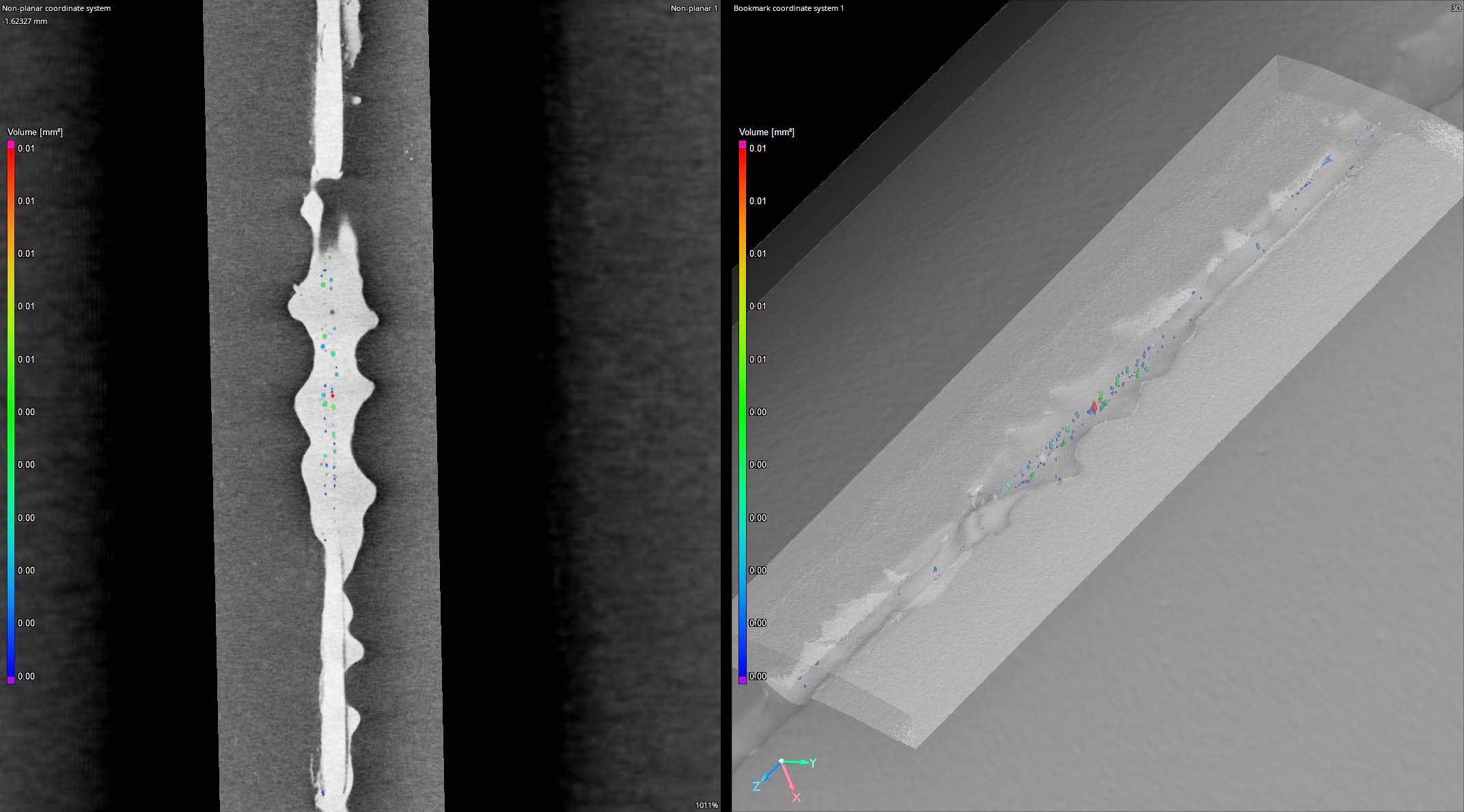
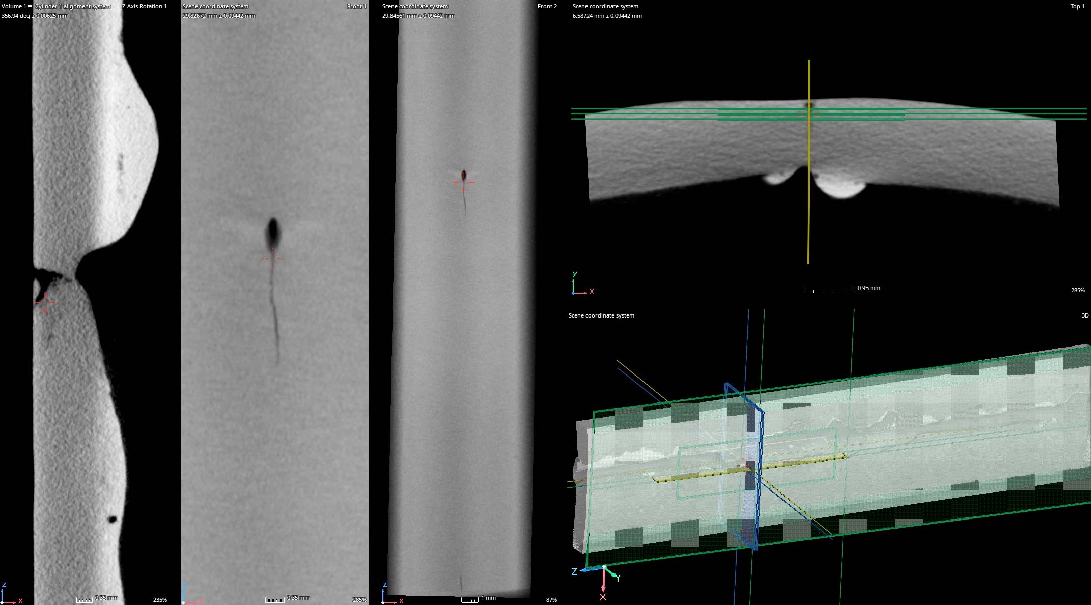
Industrial CT scanning is used to evaluate welding processes by offering higher certainty, variable data compared to 2D X-ray or micro-sectioning.
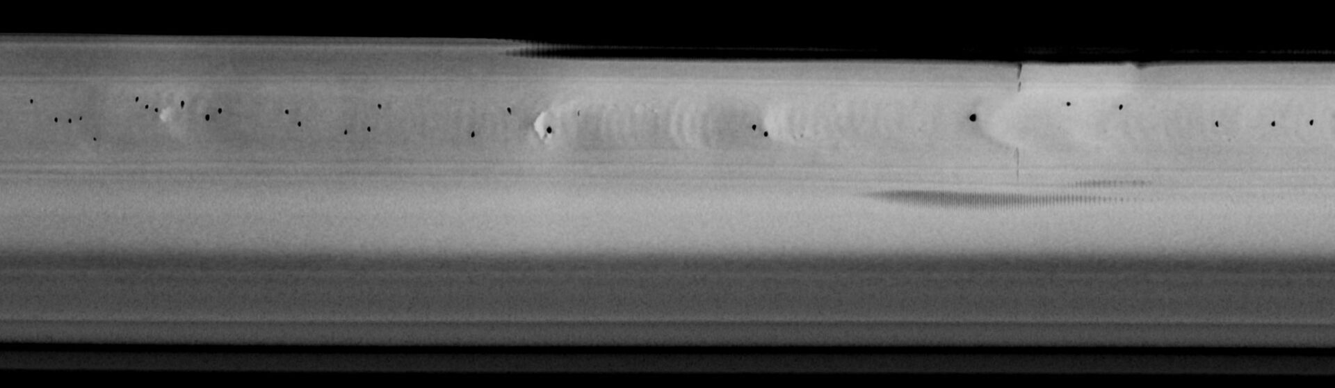
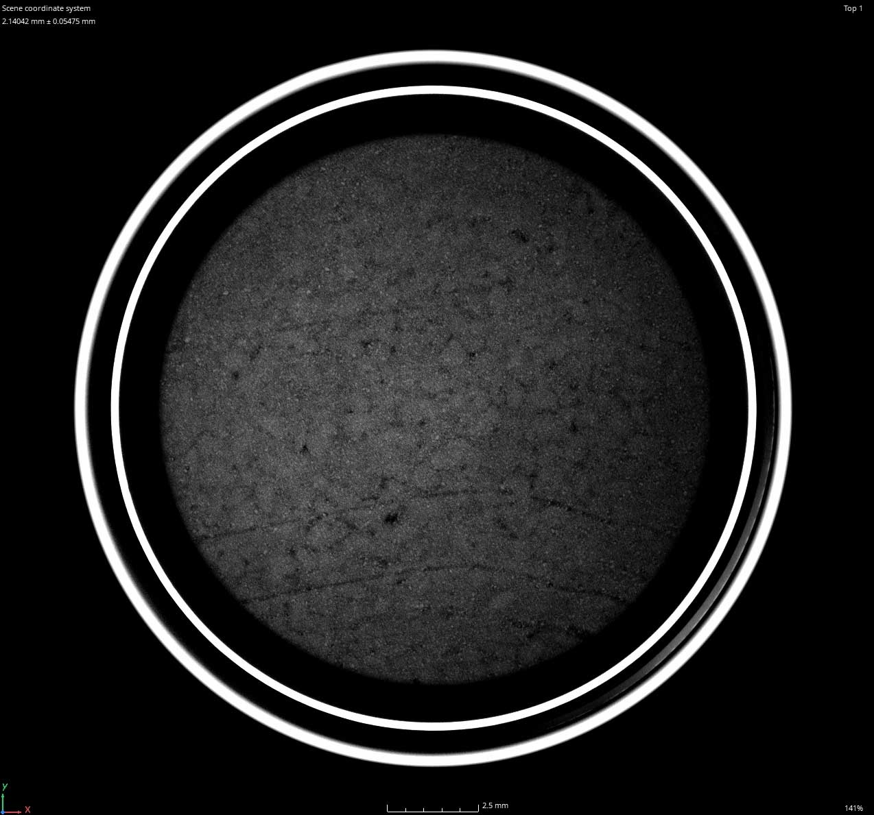
Unroll View, Volumetric Porosity in Tube Weld
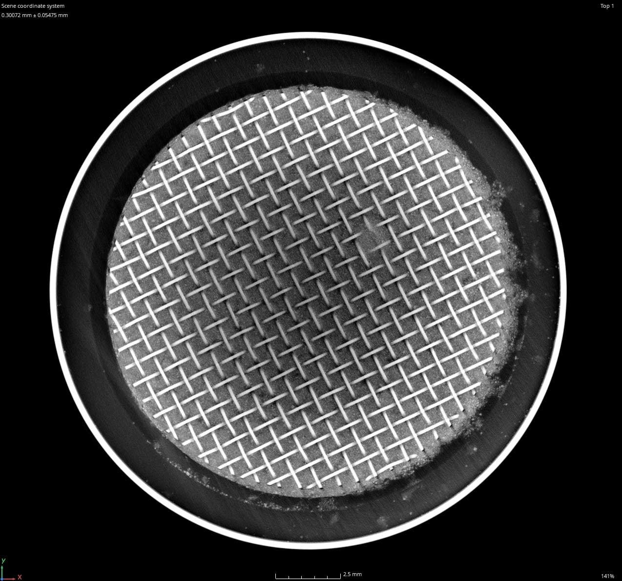
Linear Indication, Through Hole at Area of Interest
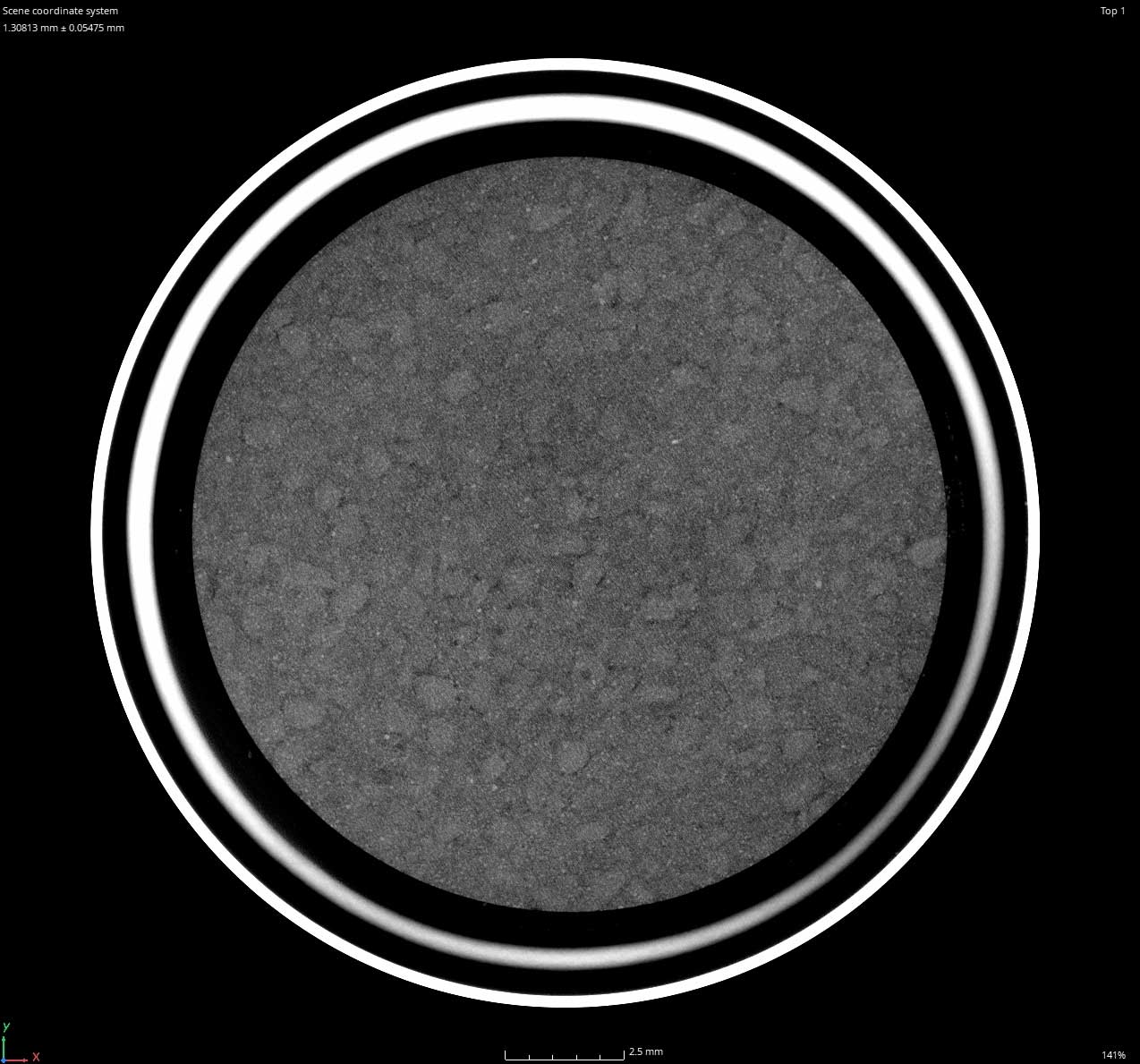
CT Slice Imaging of Porosity, 18um Resolution Area of Interest
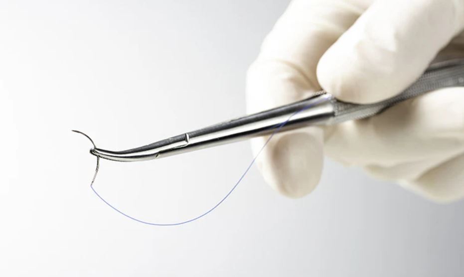
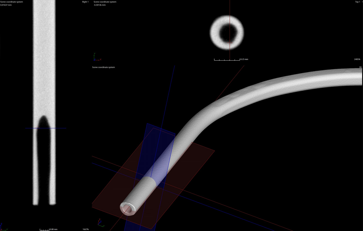
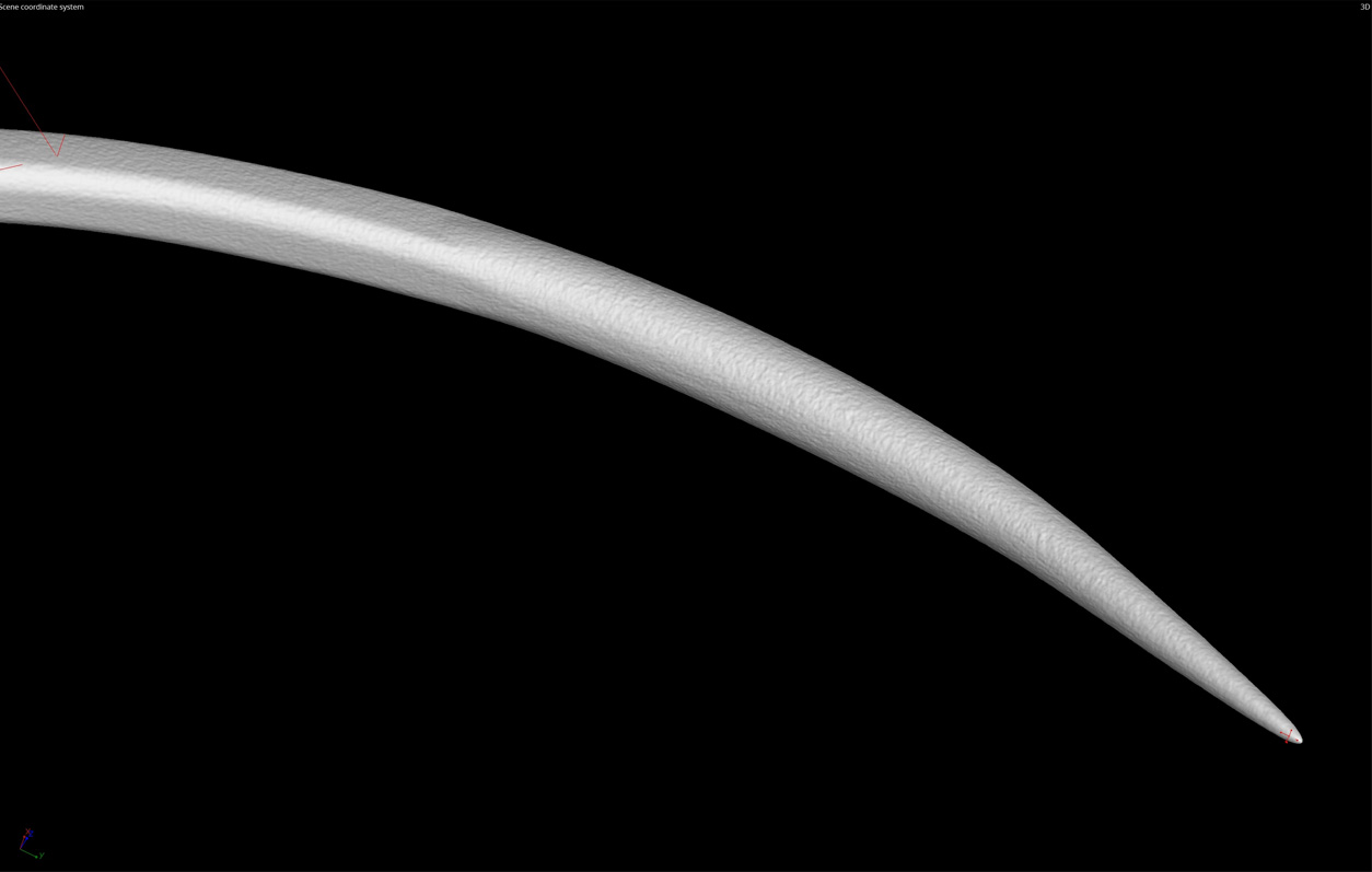
Industrial’s micro-CT scanning systems are able to resolve down to 3um resolution for the inspection of the smallest manufactured products like needles, fine drill bits, micro-springs, and gears.
The below imaging demonstrates a suture needle. It’s geometry and surface topography can be measured or visually reviewed for defects.
Every sort we receive starts with the same question – is digital radiography or CT scanning the optimal method for this project? This sort focuses on a batch of fuel injectors with pinched wires.
Radiography can be a very fast (less expensive) inspection method with a single frame shot taking just 88 milliseconds. However, if the geometry is complex, sometimes it is not possible to characterize defects in a 2D view.
CT scanning can be a longer process (more expensive – 360 degrees of x-ray shots + data processing) but offers a 3D perspective. This perspective allows a tangible characterization to the inspection method, allowing for higher certainty evaluations.
2D Radiography
Because the two wires are in line with each other it is not possible to rotate the sample without the tangs blocking the areas of interest. Rotating the sample 90 degrees also did not work because the copper winding is behind the wires which reduced penetration. If the part configuration were different radiography could have quickly sorted this batch of parts.
3D CT Scanning
High resolution, high speed CT scanning was the method chosen for sorting this batch of parts. The below views are best effort results from the R&D portion of the project to prove capability. The defective sample was used as a representative quality indicator (RQI – a gauge used to prove the process.) We used this RQI to then adjust parameters for speed to improve run rate and reduce cost. Ultimately, we were able to reduce resolution and batch scan three samples at once in a three minute scan. Parts were serialized, sorted, and returned to the customer with accompanying serialized imaging.
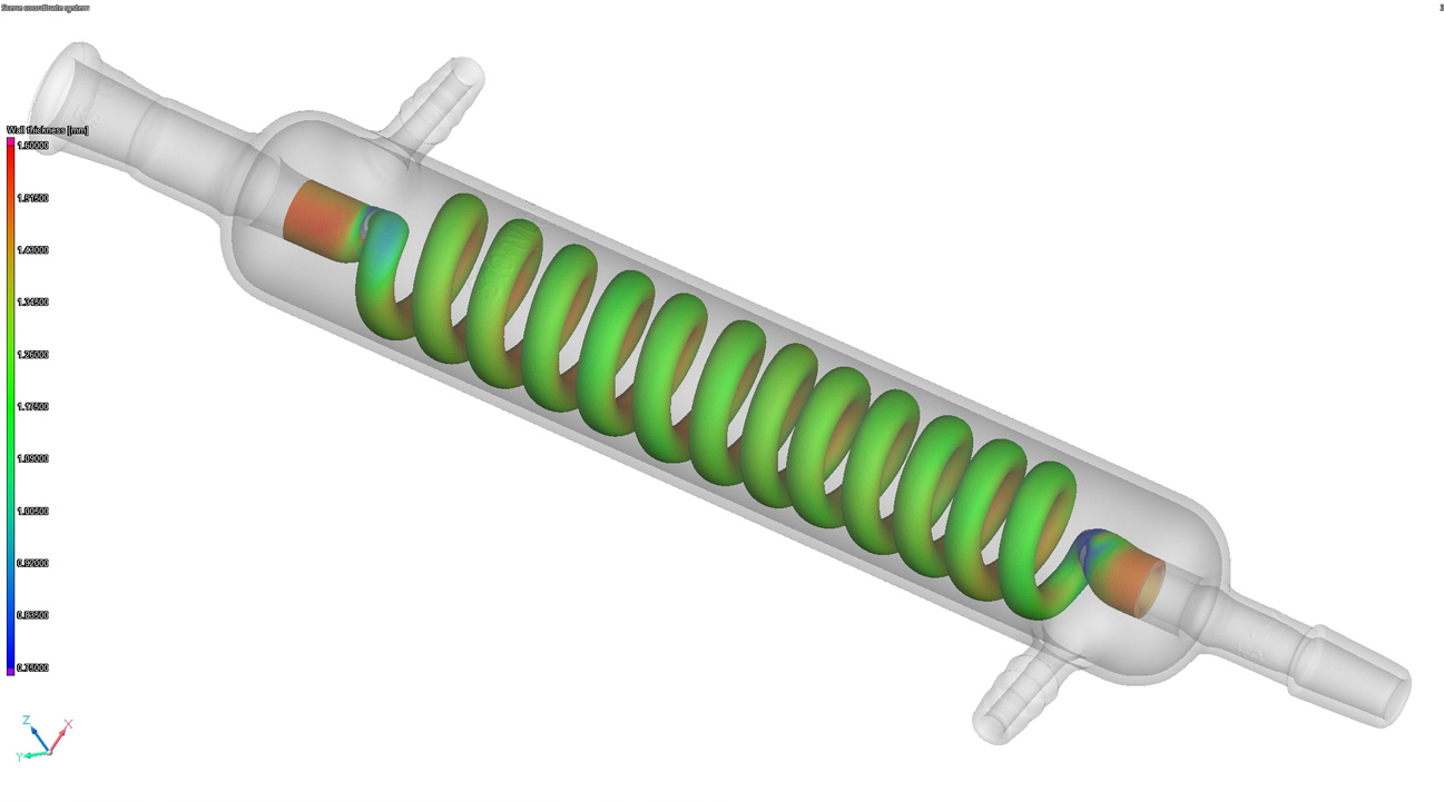
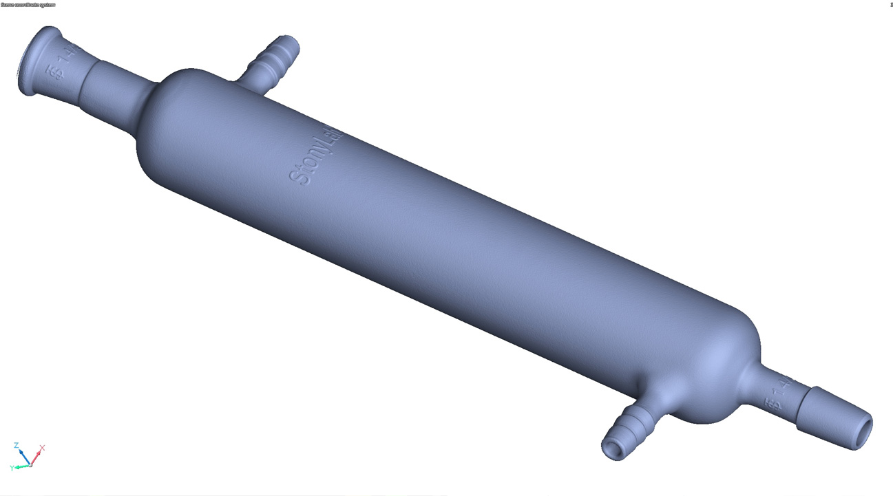
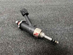
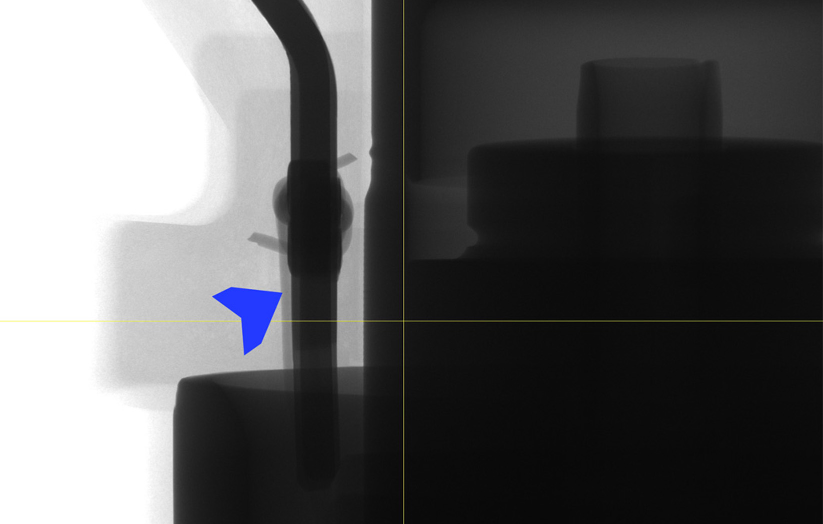
Miniature fluid control components are used in every industry – from scientific instruments like respirators, to defense systems like missile seekers, and automotive EV battery heaters and coolers.
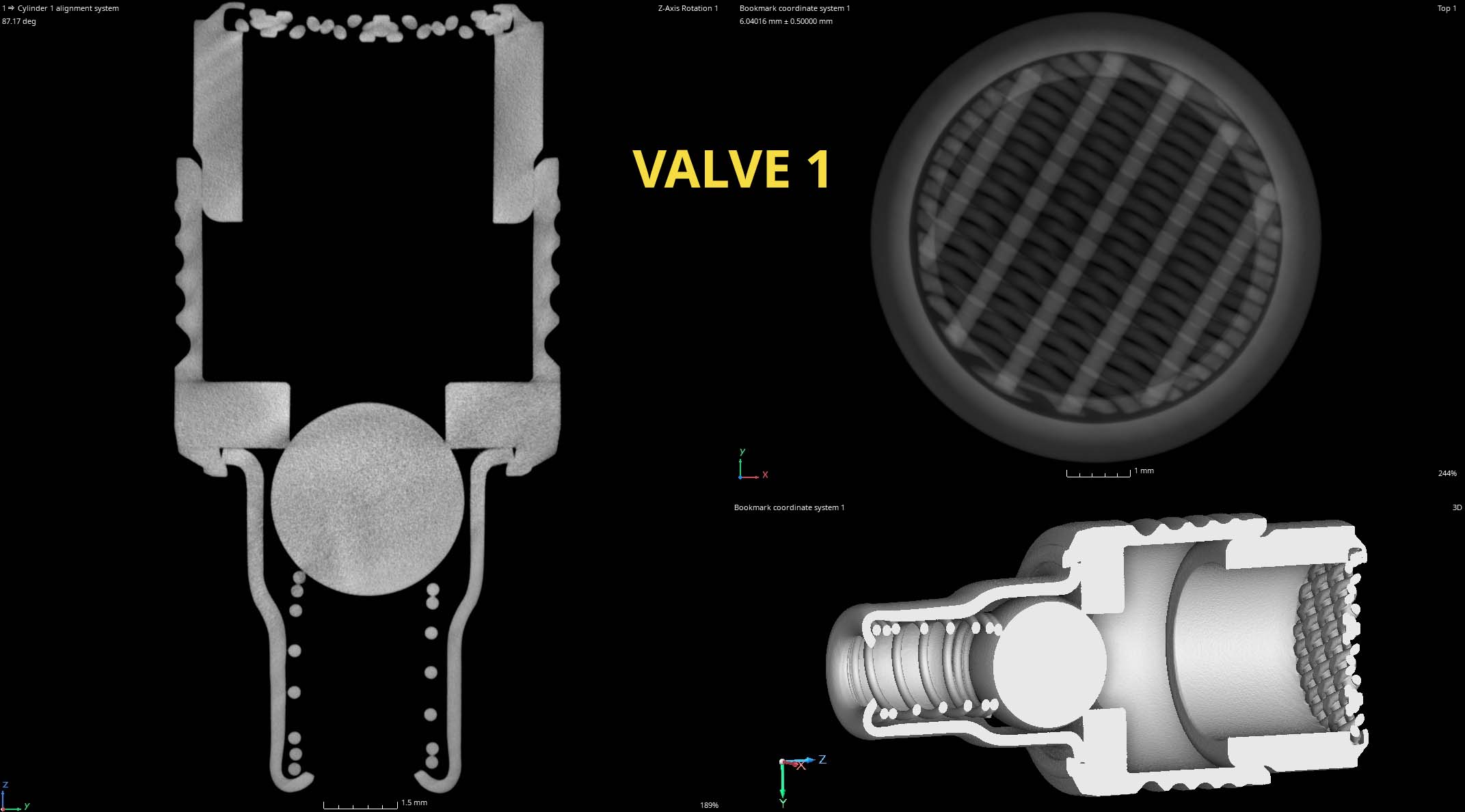
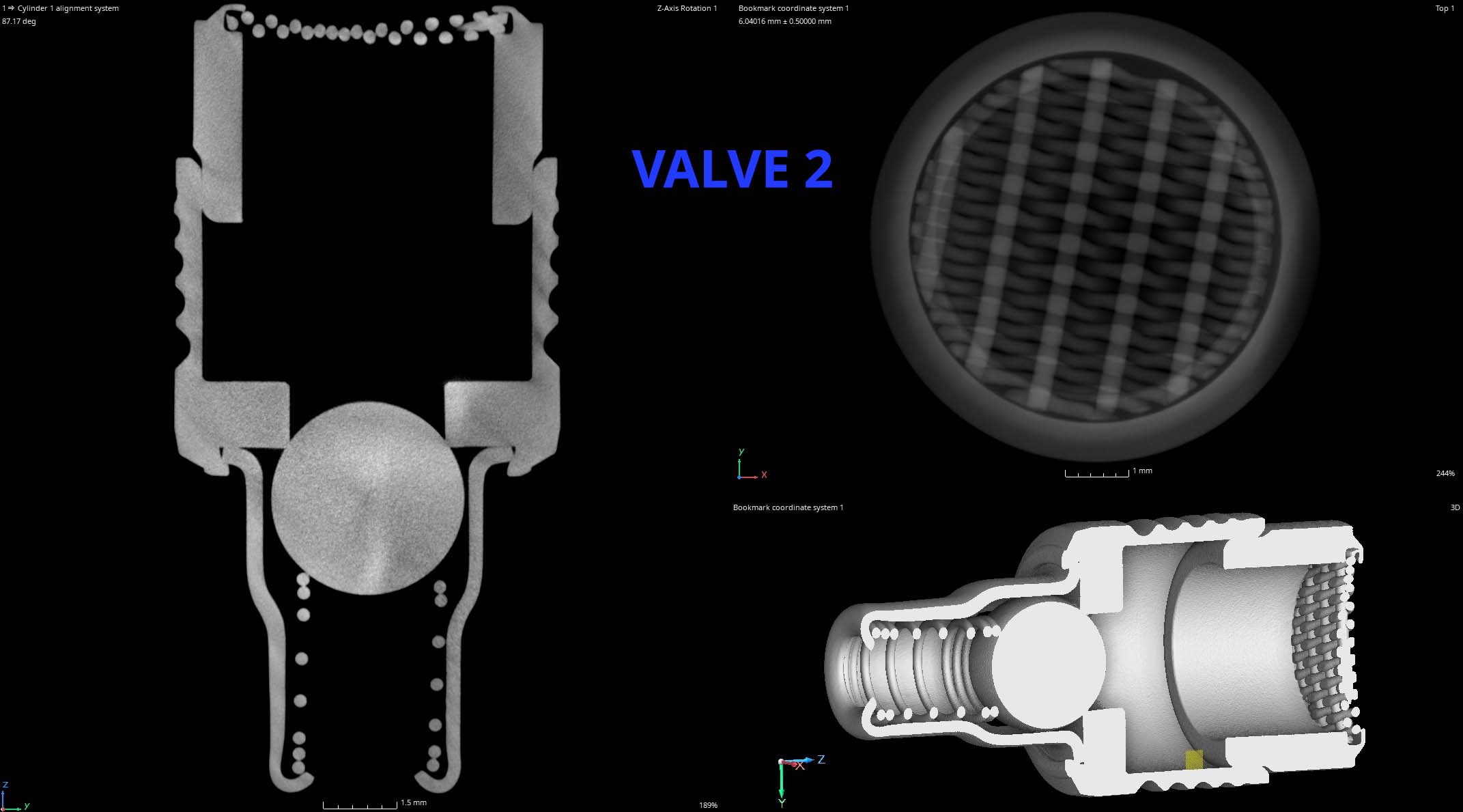
This case study characterizes two stainless steel, mesh screened micro check valves smaller than a dime. We demonstrate CT slice comparisons of the components as well as our measurement capabilities using PolyWorks.
We are able to measure wall thickness, check for component orientation like the spring, ensure the ball seats properly, and image the screen weld.
If one part is functioning differently than another we can create a color coded heat map showing the differences.
Part to Part Profile Comparison
Profile of a Line for Shape & Orientation
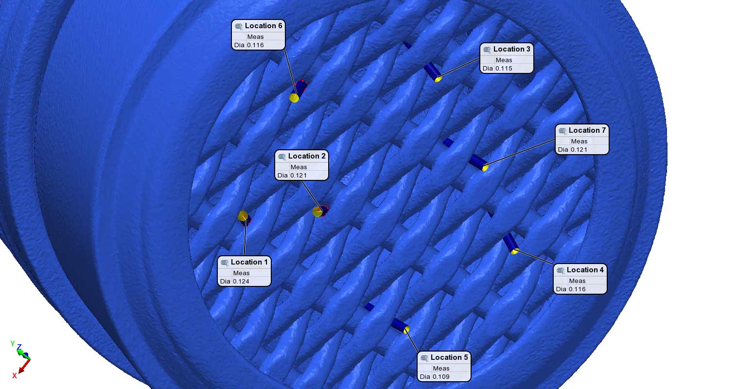
.125um Screen Weld Characterization
Tangible Measurement of Screen Pore Tolerance
We defined best fit cylinders into the screen gaps to understand the actual diametral width of the screen. We found that the screen, indeed, does not allow any contaminant above 125um diameter through.
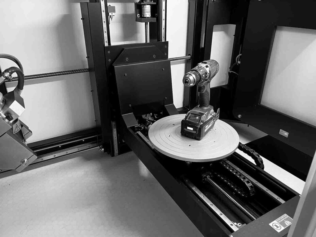
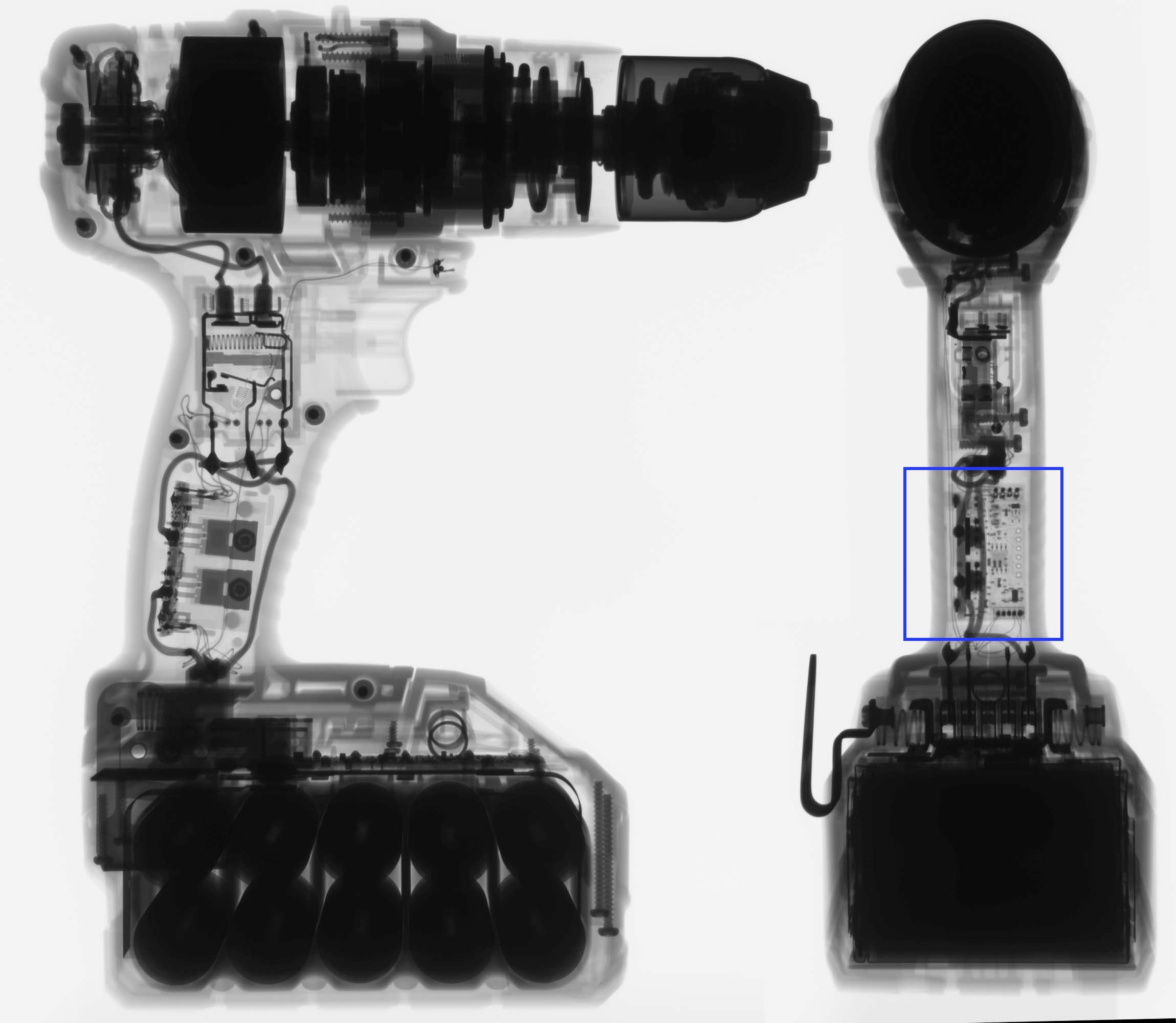
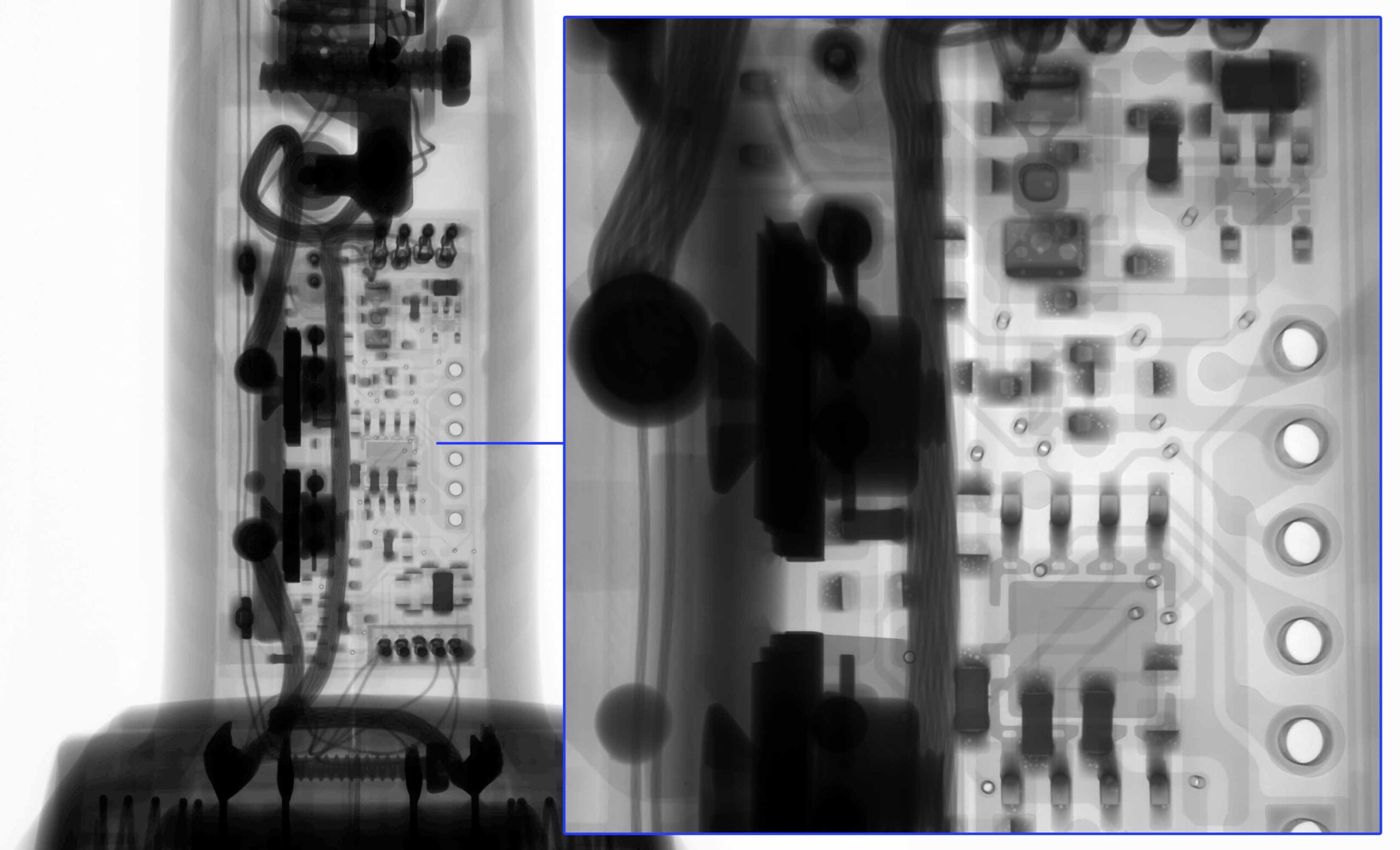
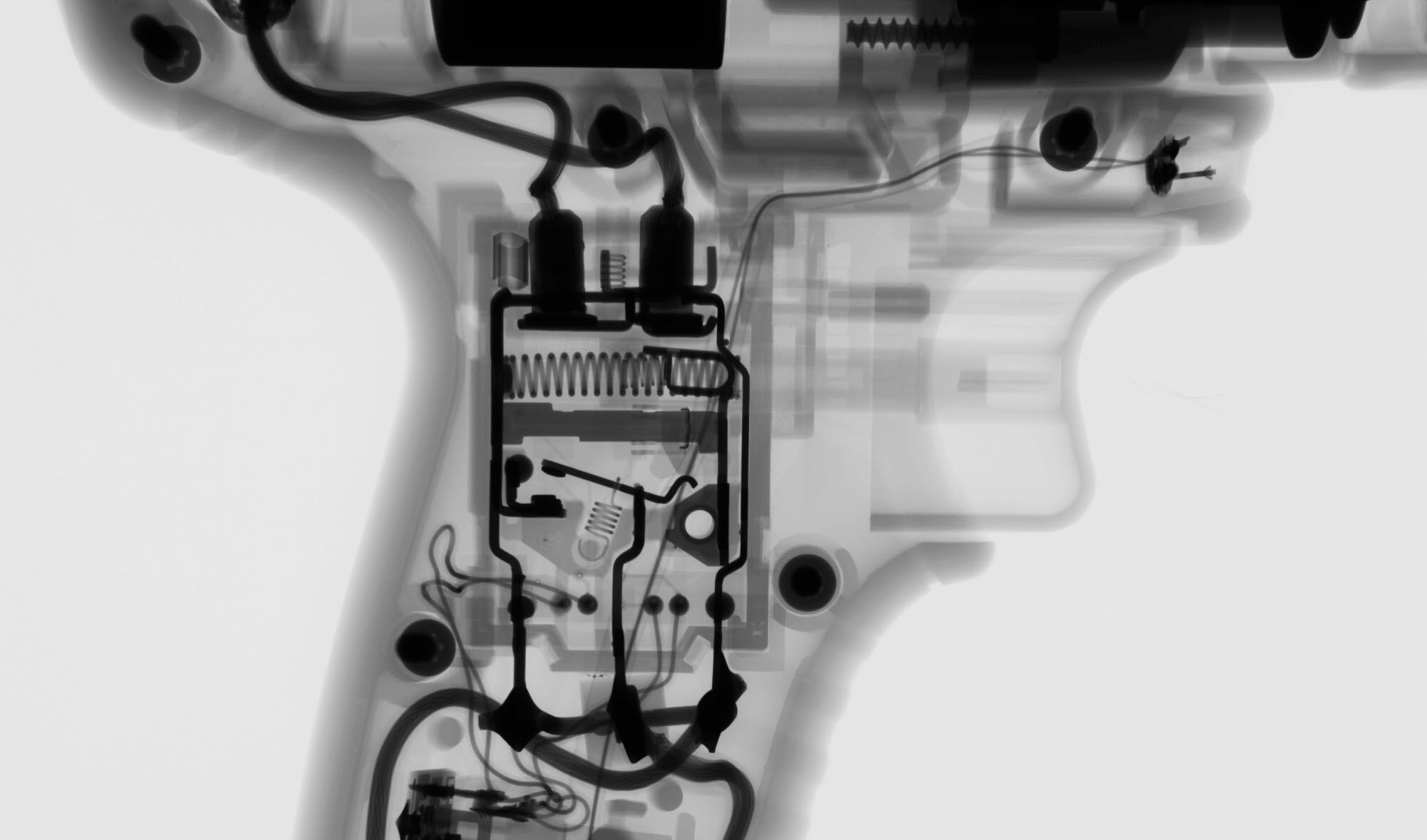
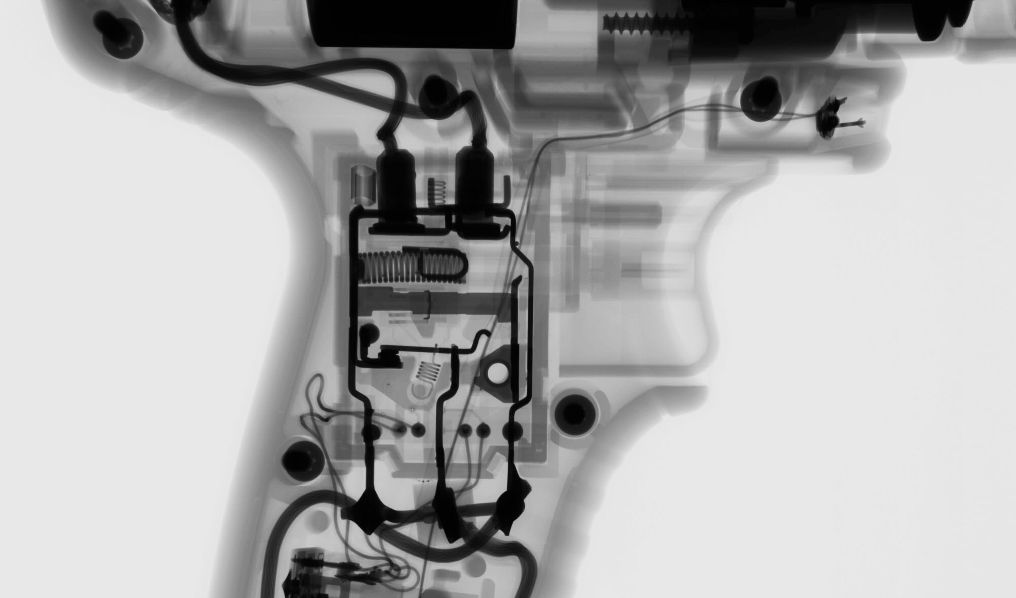
Industrial X-Ray & CT inspection services allow our clients to inspect the internal geometry of their products. This case study explores a power drill. We’ve worked on a variety of home goods like coffee grinders, chainsaw starters, shaver bladers, and mouthwash caps.
High resolution x-ray and CT also allows technicians to measure internal, inaccessible geometry, evaluate fine details like wire bonds and porosity in solder joints, and characterize leak paths in consumables.
General Digital X-Ray Images of Power Drill
Our digital x-ray systems have variable resolution ranging from 3um to 125um. This allows us to image very small and very large objects. This drill could be imaged at low resolution for general component placement (springs are in position) or at high resolution to detect and calculate porosity in the PCB joints.
Pre-to-Post actuation is useful for understanding the dynamics of a complex assembly. For example, happens when something is powered up? How much clearance is there when a lever is pressed? Fill the blank with your own scenario and consider letting Industrial Inspection quantify it for you.
INDUSTRIAL CT SCAN OF POWER DRILL
2D Digital radiography is great for a general understanding of components. However, 3D CT scanning allows inspectors to produce tangible, complex measurements of devices. For example, we could measure the concentricity the chuck components, the profile of the handle, or the depth wires are placed into a connector.
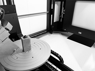
CHARACTERIZING AM COMPONENTS USING INDUSTRIAL CT SCANNING
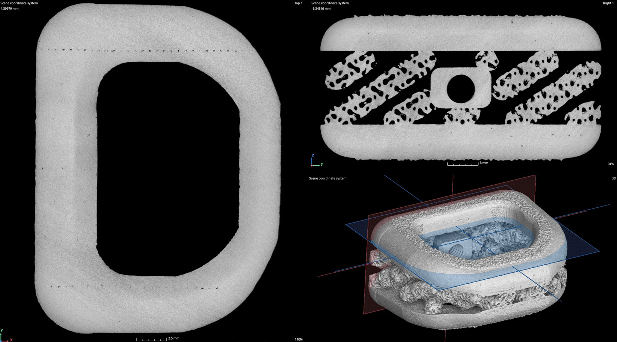
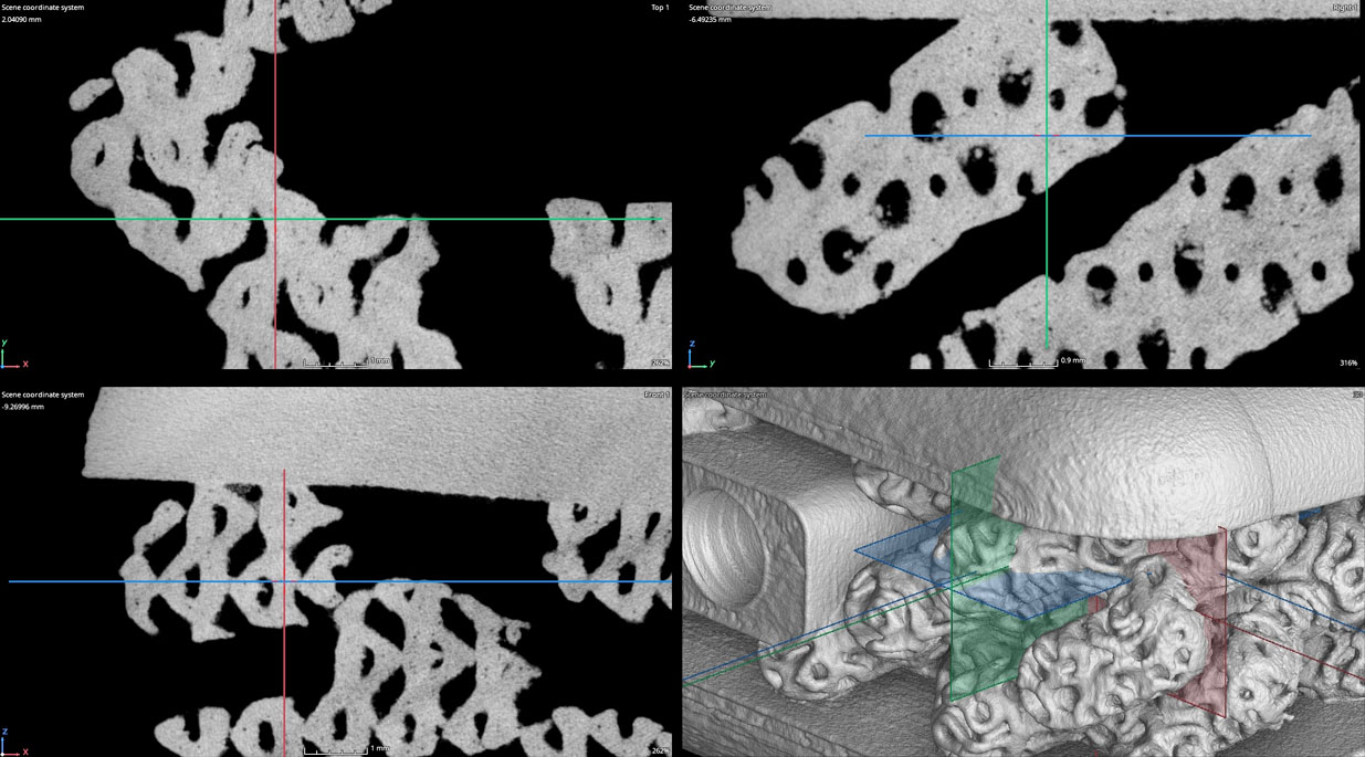
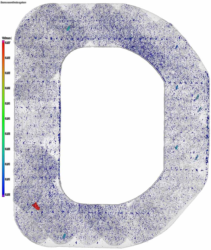
Industrial CT Scanning is used to characterize 3D Printed / Additively Manufactured components. A strength of these components is the ability to manufacture complex geometries that more traditional manufacturing methods are incapable of producing. However, because of the part complexity more traditional inspection methods like tactile probes and vision system are inadequate. CT scanning can be used to dimensionally inspect and non-destructively evaluate these components for rejectable flaws (porosity, trapped powder, wall thickness, & profile.)
POROSITY ANALYSIS
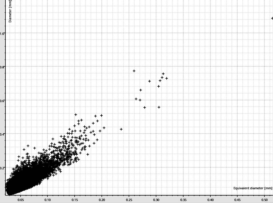
Porosity can be volumetrically extracted and analyzed for porosity percentage, distribution, 3D rendered for visual comparisons between process changes, or exported to .stl to be used in other software packages.
Distribution of pore size and equivalent diameter
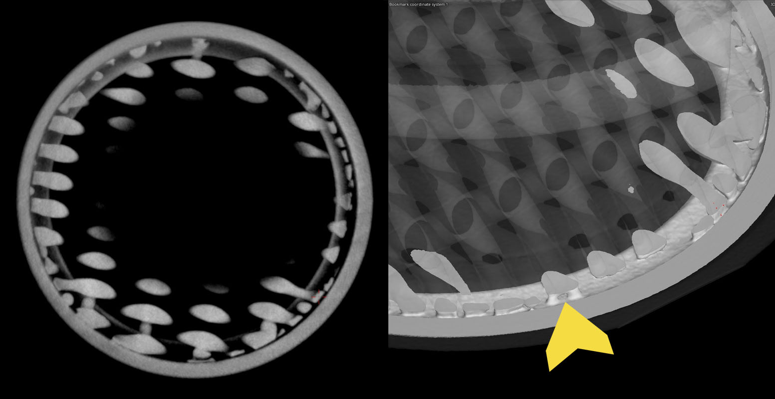
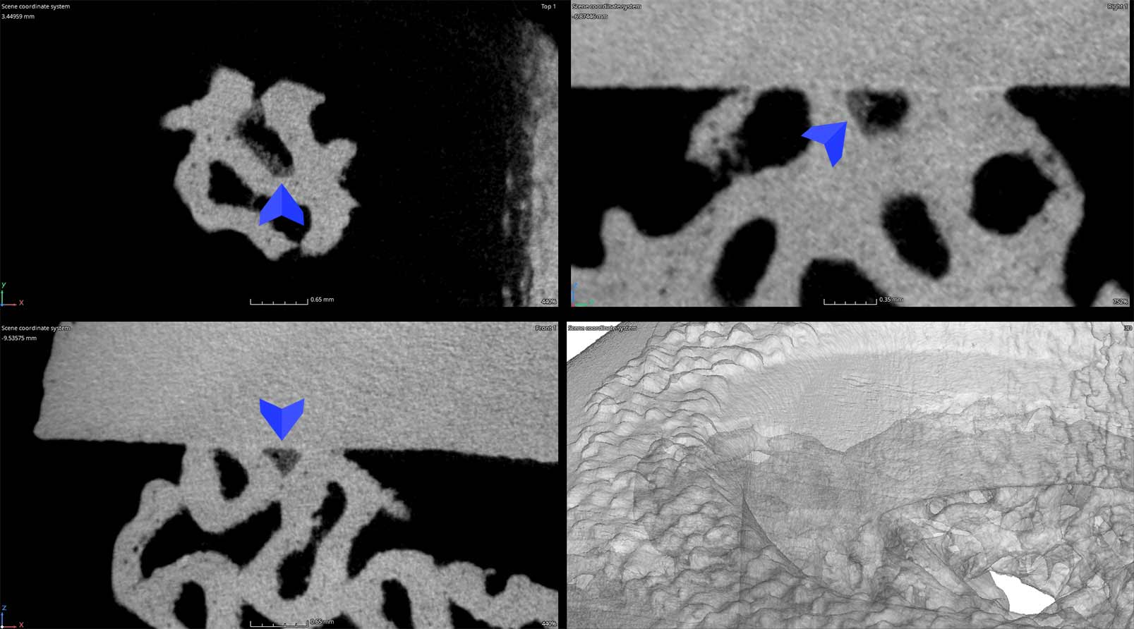
TRAPPED POWDER INSPECTION
Industrial CT scanning is used to analyze additively manufactured products for trapped powder. If trapped powder is not completely removed from products, its release during product service lifetime could cause serious problems. For medical implants with materials that are supposedly biocompatible, metallic powder can cause inflammation and prevent normal blood vessel formation. [Source] The image below shows an area of interest that should be open to the surface but closed during manufacturing. The trapped powder is seen as a slightly lighter shade of gray compared to the neighboring geometry.
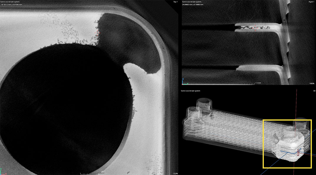
Characterizing Leak Paths in Brazed Copper Heat Exchangers
Heat exchangers are devices that transfer heat from one medium to another using a network of channeled circuits. We’ve CT scanned most types of heat exchangers including shell & tube to image tube array welds and plate type exchangers to evaluate brazes and leak paths.
This case study uses a common copper plate type heat exchanger which contains a network of channels that fluid passes through.
As seen below in the general part scan there are indications of porosity and gaps in the corner and edges which may be causing the part to leak.
Once an area of interest has been determined we can increase resolution to provide better detail of the failure. This partial scan at just the corner reveals that the entire corner is missing brazing material and there are also leak paths in proximity. The customer uses this information to adjust their manufacturing process.
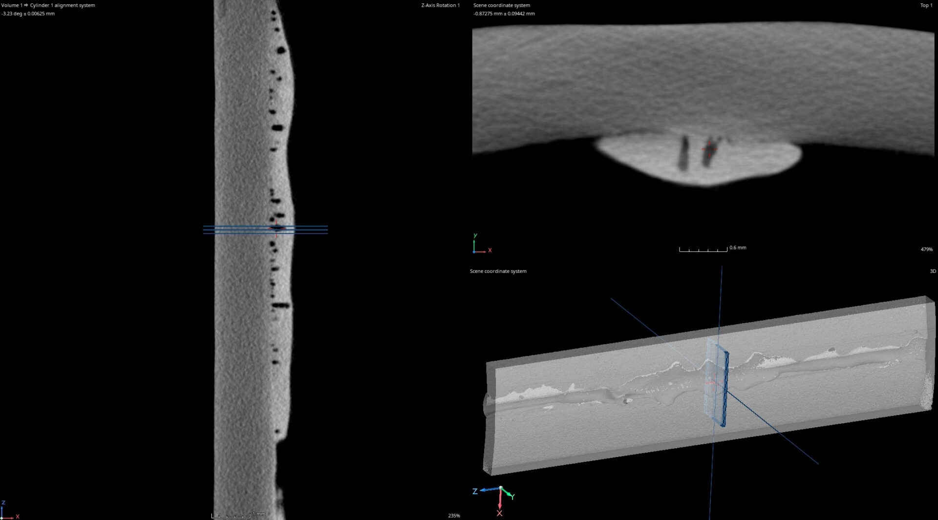
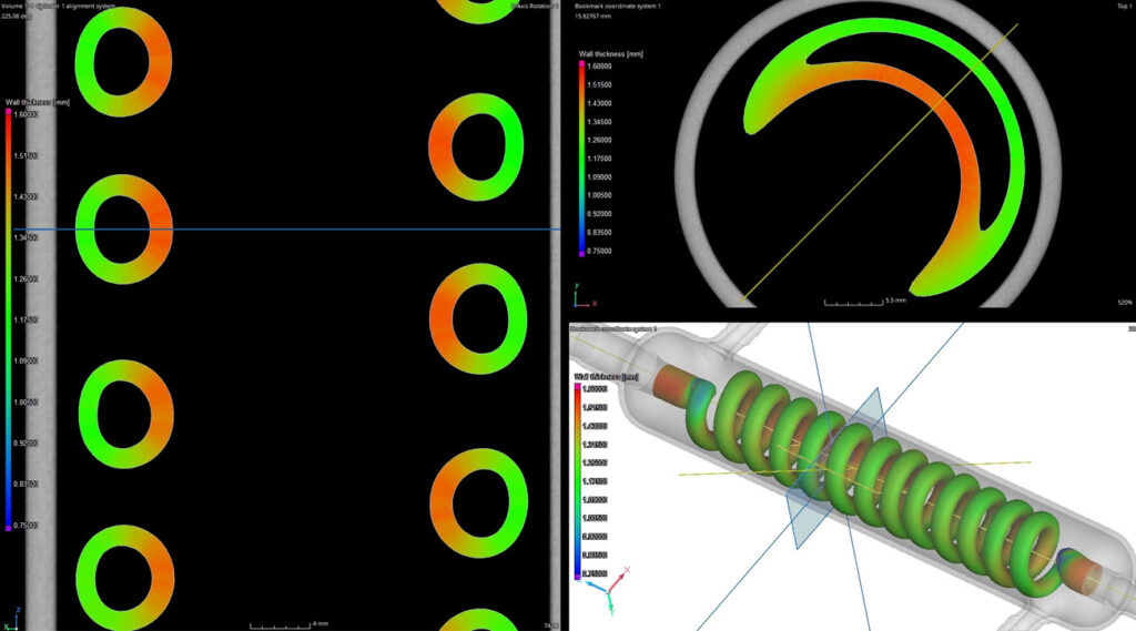
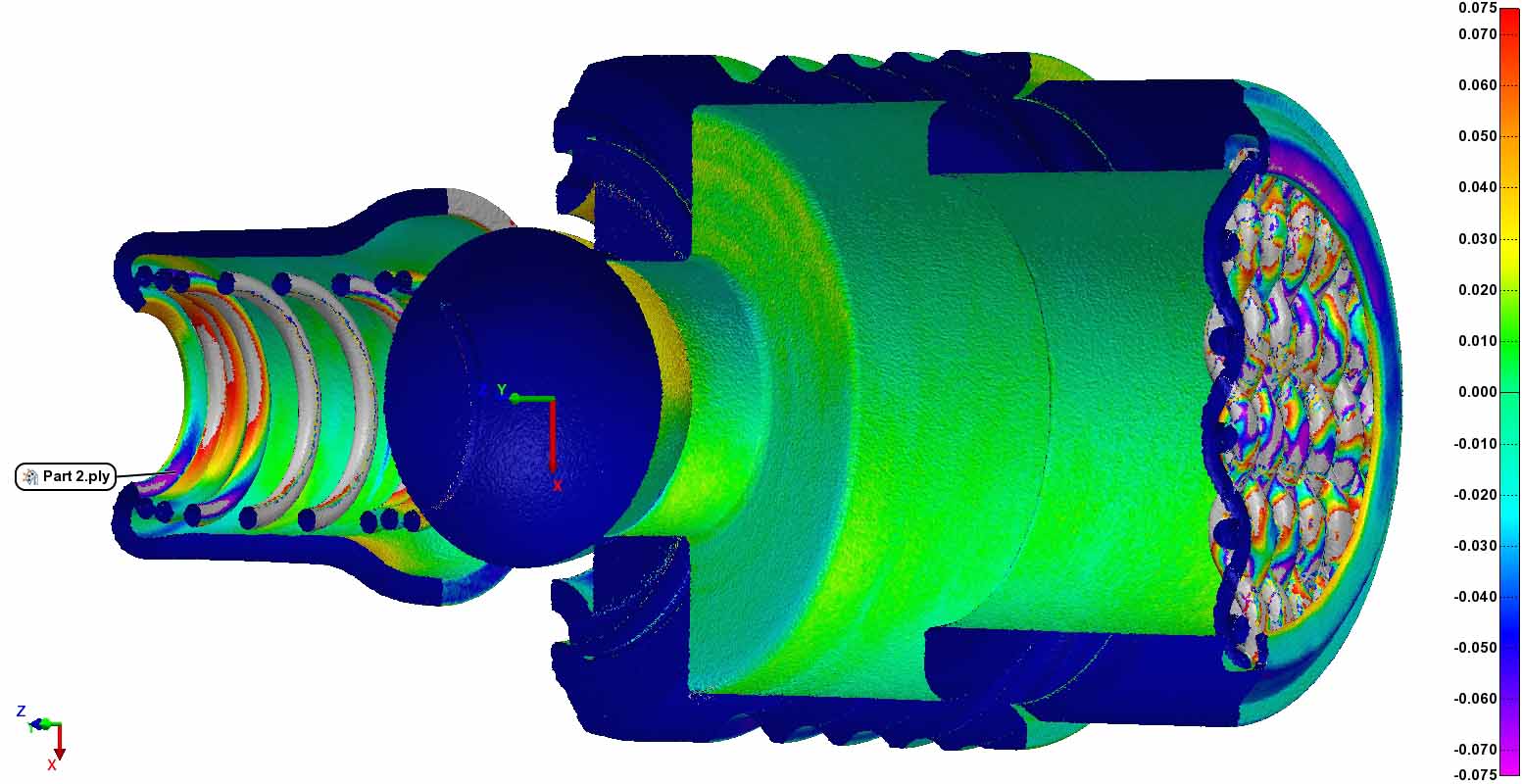
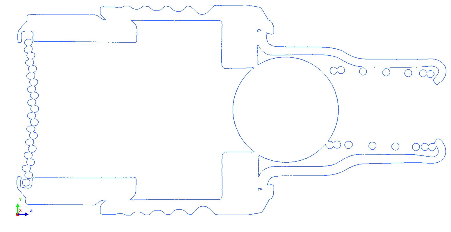
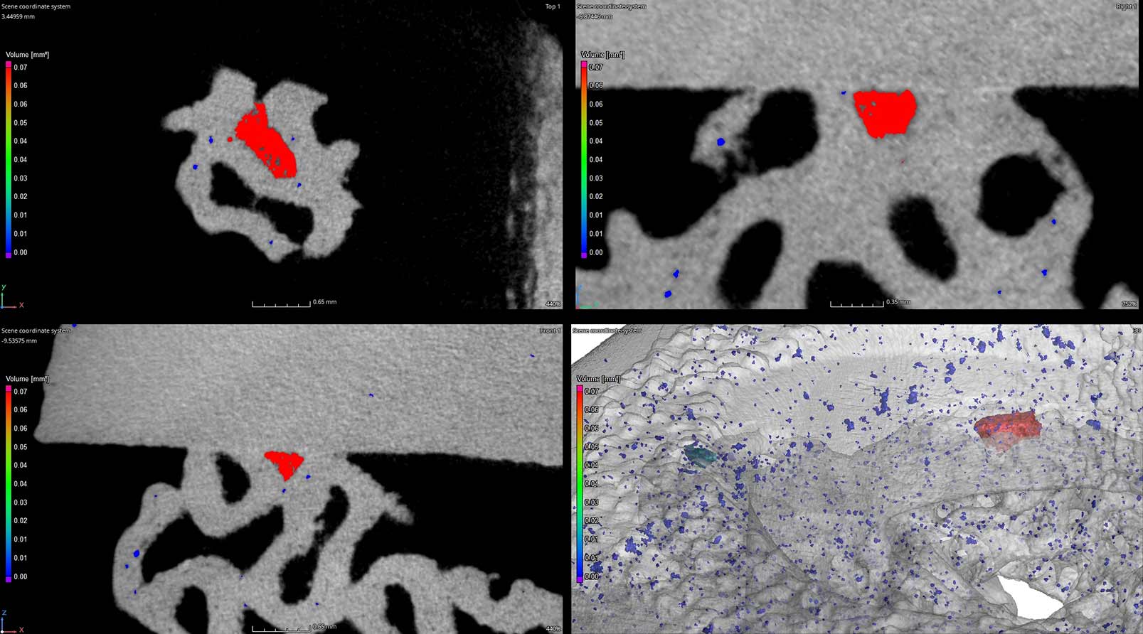
Bellows are a type of expansion joint used in piping applications for a variety of industries like oil & gas, aerospace and defense. Bellows allow complex systems to move according to the forces applied to them (system vibrations, pressure changes, & rapid temperature shifts).
Because bellows are used to sustain a system through the above factors their structural integrity is paramount. This case study demonstrates the method of CT scanning to image and qualify bellows welds and ply separation.
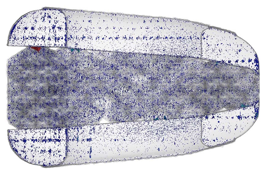
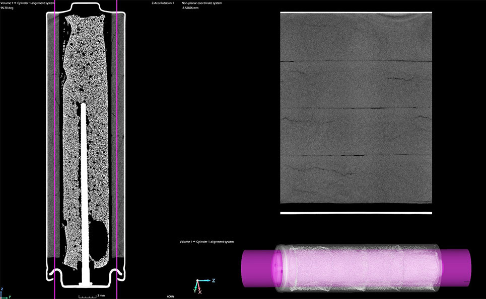
UNROLL METHOD
The “Unroll” technique offers a planar viewing method for cylindrical features or parts. Below is an unrolled, higher zoom view of the weld, porosity, and sleeve seam.
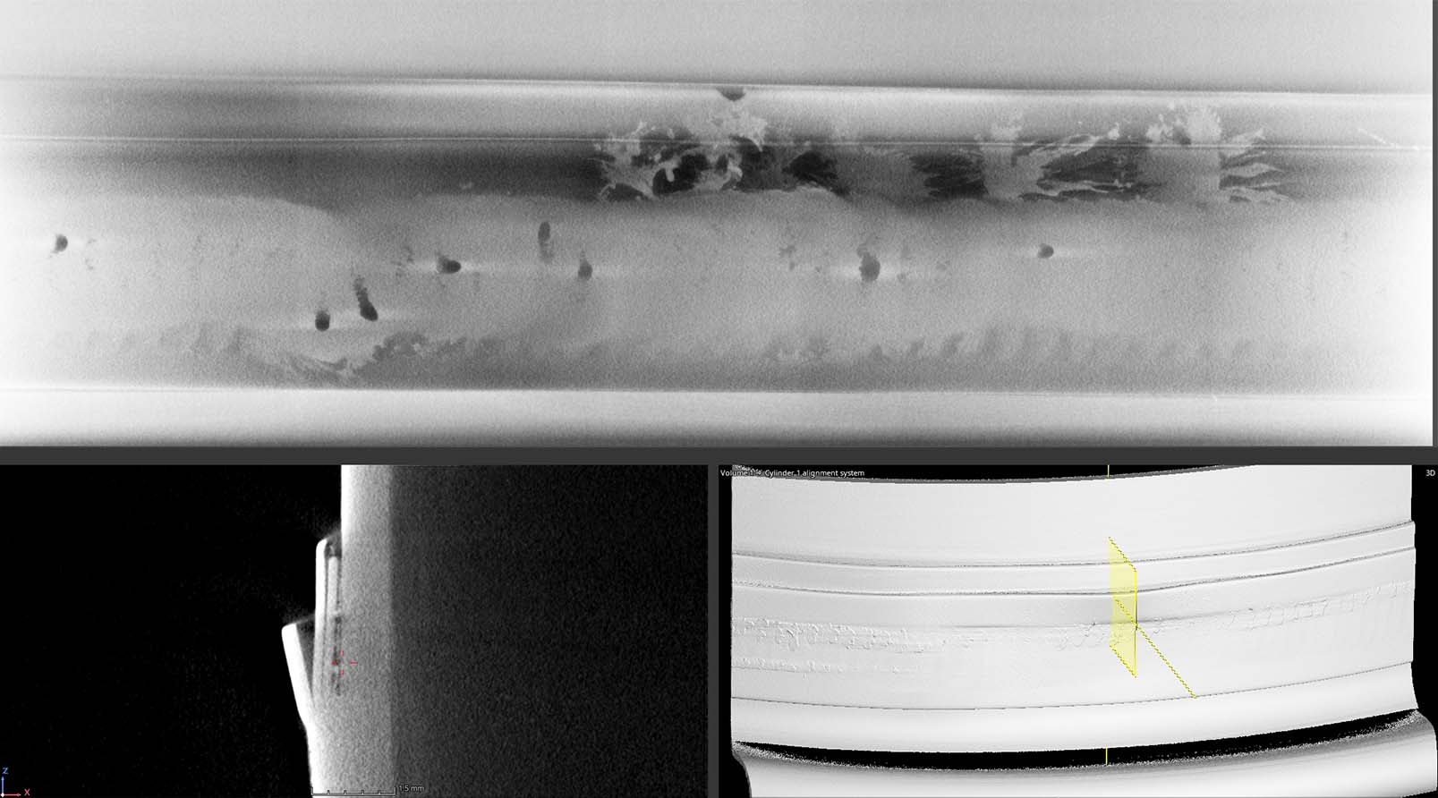
FOCUS SCAN (20um RESOLUTION)
During process development engineers often request the highest possible resolution of an area of interest. This characterization helps inform the engineer for process changes and product viability.
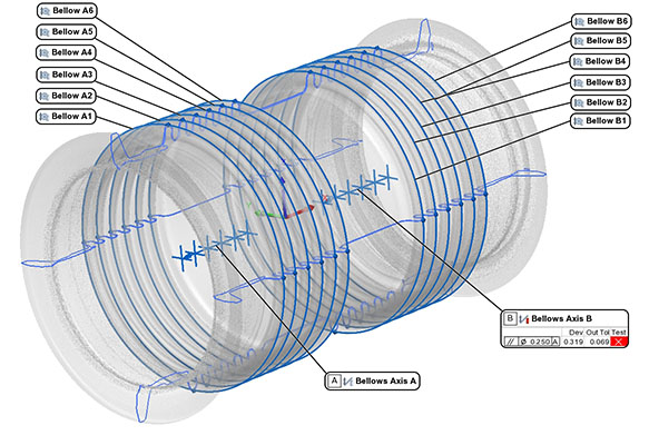
DIMENSIONAL INSPECTION
Industrial CT data, and surface data acquired using laser scanning (click here to learn more), is exported to .stl for dimensional inspection. We are able to inspect complex, inaccessible geometries that more conventional systems cannot reach. For example, we measured ID axis perpendicularity and inside ply diameter centerpoints of each bellow and found this bellow consistently deviates in +Y.
Modern electrification is taking over many industries and battery technology is rapidly evolving to ensure new energy sources have a reliable storage mechanism. Industrial CT imaging, a technology that offers the ability to see inside objects non-destructively, is critical for evaluating manufacturing processes and comparing technology changes.
This case study demonstrates the viability of scanning various battery types from small battery cells to large EV battery modules.
COIN & BUTTON CELL BATTERIES
Micro-CT imaging is a critical tool for characterizing the geometry of small batteries. With variable resolution between 3um and 125um, no battery is too small to be imaged.
CT characterization is used for evaluating new technologies, comparing process changes, and determining points of failure.
CYLINDRICAL BATTERY CELL (AA)
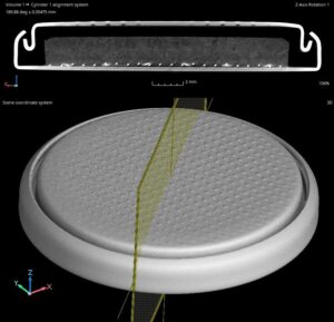
There are several imaging methods and variables to consider for a given application. When we scan cylindrical cells a useful tool called “Unroll” is often deployed.
Unroll allows the inspector to planarize cylinders. For example, imagine cutting a toilet paper roll and laying it flat on your desk. The digital equivalent allows the inspector to scroll through a planar view at any distance from the specified axis.
The video to the right demonstrates “Unroll.”
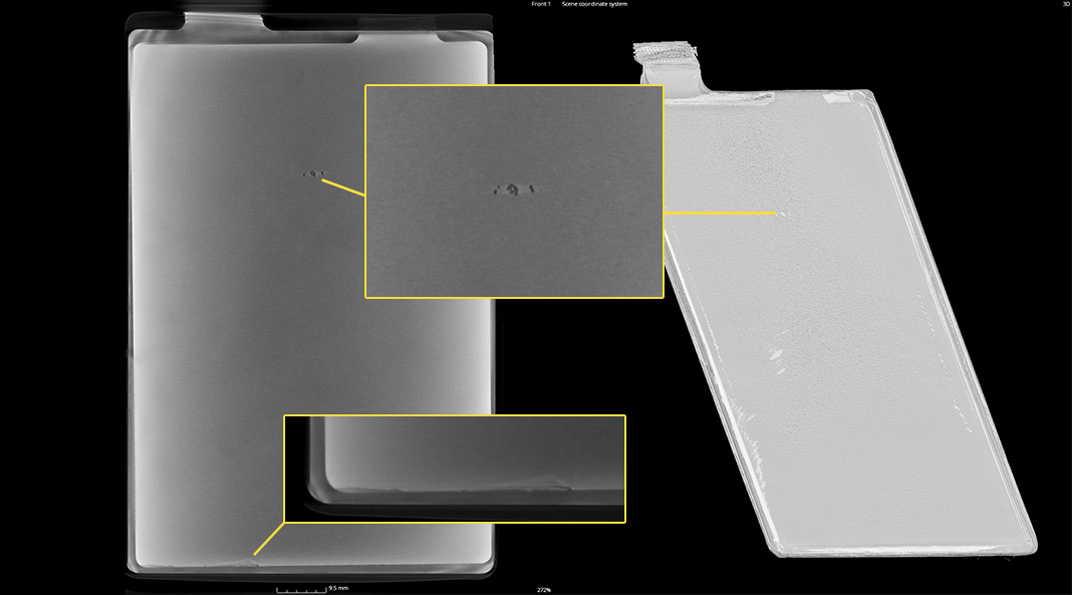
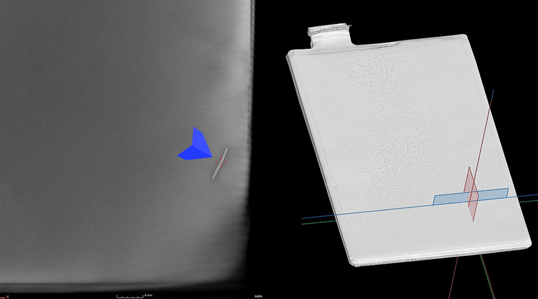
POUCH & PRISMATIC CELLS
Foreign object debris is one of the primary causes of battery thermal runaway resulting in increased temperatures, destruction of the battery, and fires.
Reliable detection of foreign objects is critical for the safe manufacture, storage, and long term use of battery cells. If there is a manufacturing failure it is best to inspect cells before assembling them into full battery modules. Because cells are smaller and easier to handle resolution and x-ray penetration can be improved.
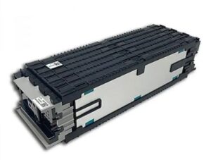
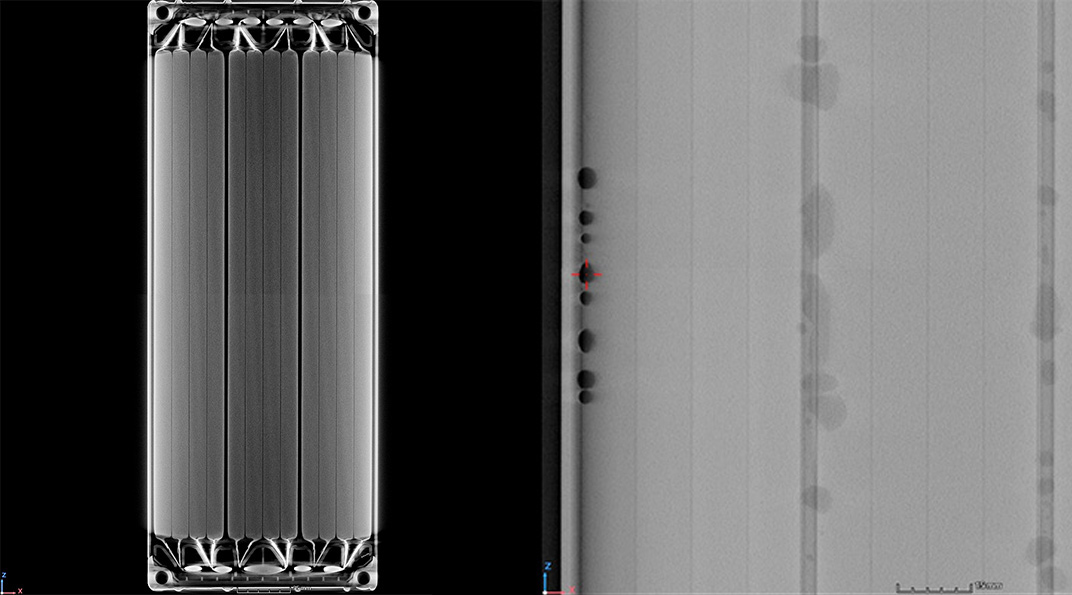
BATTERY MODULES
Industrial Inspection staff has CT scanned thousands of battery modules. Customized criteria are used for each project with regard to what the issue may be. Some typical rejectable indications include: