X-ray inspection is a non-destructive testing method, meaning it allows for the examination of castings without causing damage to the parts. This is especially important for expensive or critical components where destructive testing methods would be impractical or cost-prohibitive. X-ray examination allows for the detection of part flaws or defects like gas porosity, shrinkage cavities, cracks & hot tears, inclusions, and voids.
Industrial Inspection offers a roster of technicians certified per the American Society for Nondestructive Testing (ASNT / SNT-TC-1A) and National Aerospace Standards (NAS-410). Our technicians have x-rayed everything from infrastructure pipework, automotive components, and rocket manifolds.
There are a wide variety of standards and gauges used for digital radiography depending on the material type, thickness, and customer driven requirements for sensitivity. Industrial Inspection has a robust library to respond to almost any requirement and, for niche requirements, can order custom gauges within days.
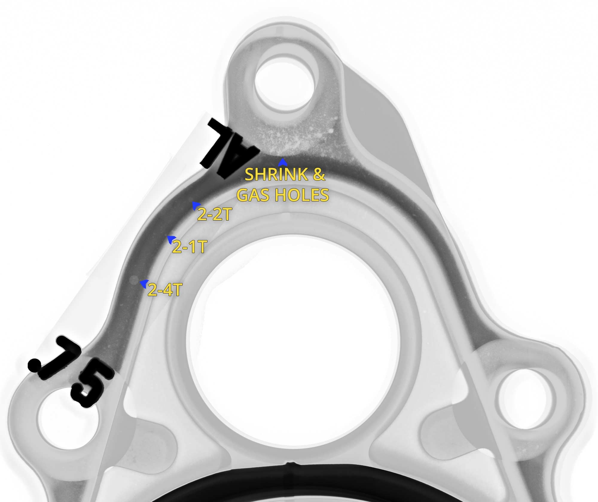
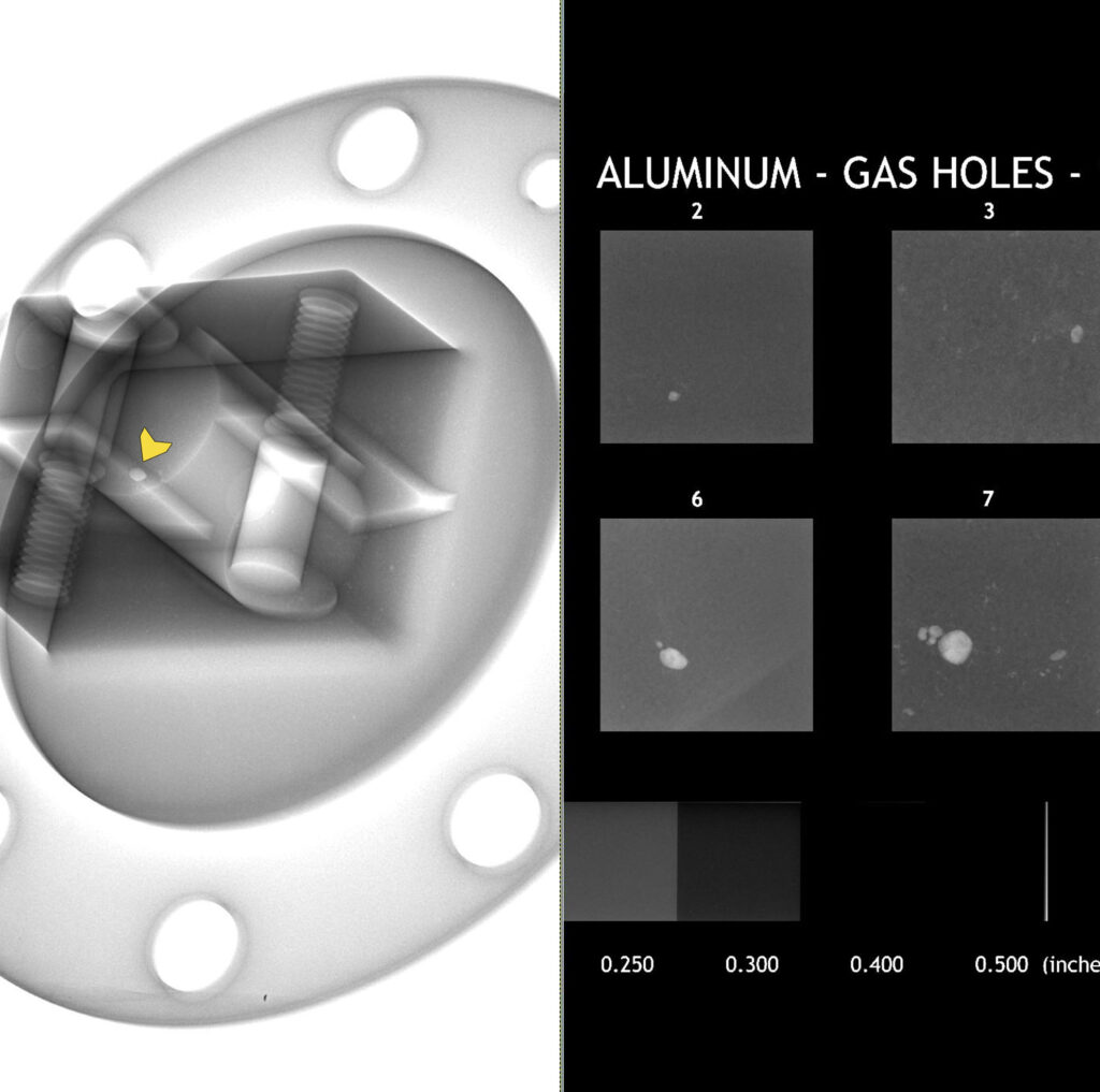
We use industry standard software for image processing, evaluation, and grading. To the left is a casting being compared to ASTM E2422 Digital Reference Images for a gas hole in proximity to the edge of a machined surface.
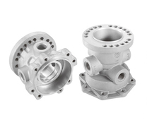
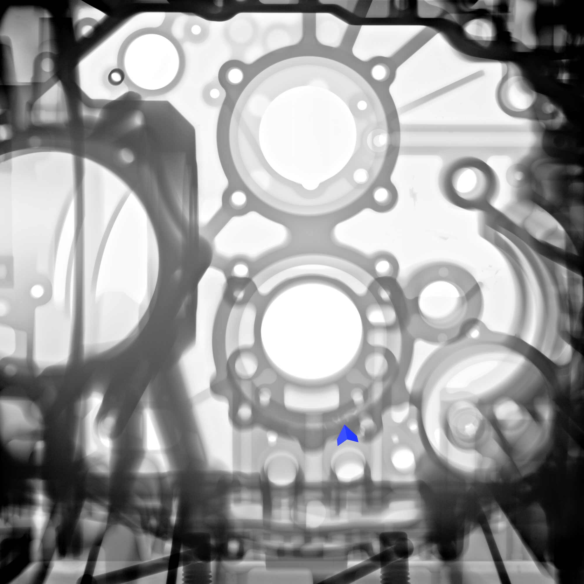
Below is x-ray imaging of a transmission housing before and after contrast adjustment. Penetrameters are used to qualify a technique for adequate penetration through various material thicknesses, and software is used to adjust brightness and contrast to look for defects not seen in the raw image.
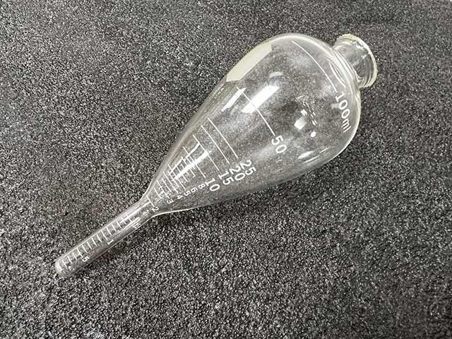
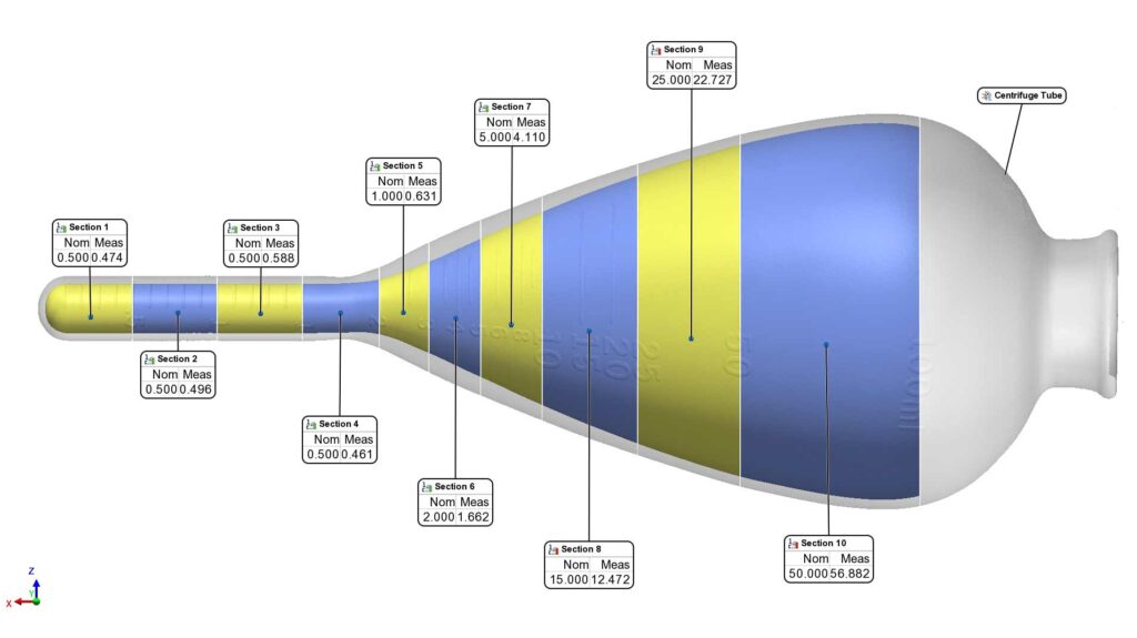
MEASURING TEST TUBES & VIALS FOR WALL THICKNESS AND VOLUME
CT scanning plays a pivotal role in assessing the wall thickness and volume of glass components, offering critical insights for manufacturing processes and product quality. Glass, known for its brittleness and susceptibility to defects, requires meticulous inspection to ensure structural integrity and performance. CT scanning provides a non-destructive means of examining these components, offering precise measurements of wall thickness and volume with unparalleled accuracy. By detecting variations in thickness and identifying potential flaws, CT scanning enables manufacturers to optimize production processes, enhance product reliability, and uphold stringent safety standards. The comprehensive evaluation provided by CT scanning ensures that glass components meet the highest quality requirements, ultimately contributing to safer and more durable end products.
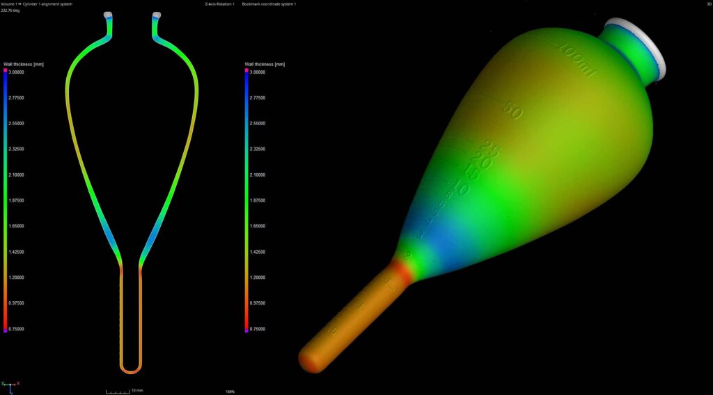
CT SCANNING TO MEASURE WALL THICKNESS
CT scanning is used for evaluating wall thickness in a wide range of materials and structures. By utilizing X-ray technology to penetrate objects, CT scanning generates detailed 3D images that allow for precise measurements of wall thickness. This non-destructive technique is invaluable for industries such as manufacturing, aerospace, and automotive, where ensuring structural integrity is paramount. This image demonstrates a total mapping of the thickness of the tube with variable results from .75mm to 2.55mm.
VOLUME OF GRADUATION MARKS
CT scanning offers a precise and non-destructive method for measuring volume in objects with complex geometries. We were able to segment, virtually cap, and extract volumetric measurements of the tube at various graduation marks.
The nominal “as-marked” volume states 100ml and the measured volume equals 100.533ml – a deviation of just 0.5% of the volume. However, sub-sections like section 5 have a deviation of 27%.
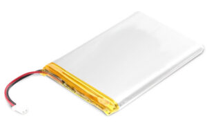
In the race towards a sustainable future, battery technologies have emerged as frontrunners, promising cleaner, greener transportation. Central to this revolution are lithium-ion battery cells, the lifeblood of many electronics. Ensuring the safety and reliability of battery cells is paramount, presenting a unique challenge for manufacturers. Enter CT scanning, a game-changing technology offering unprecedented insights into battery cell integrity.
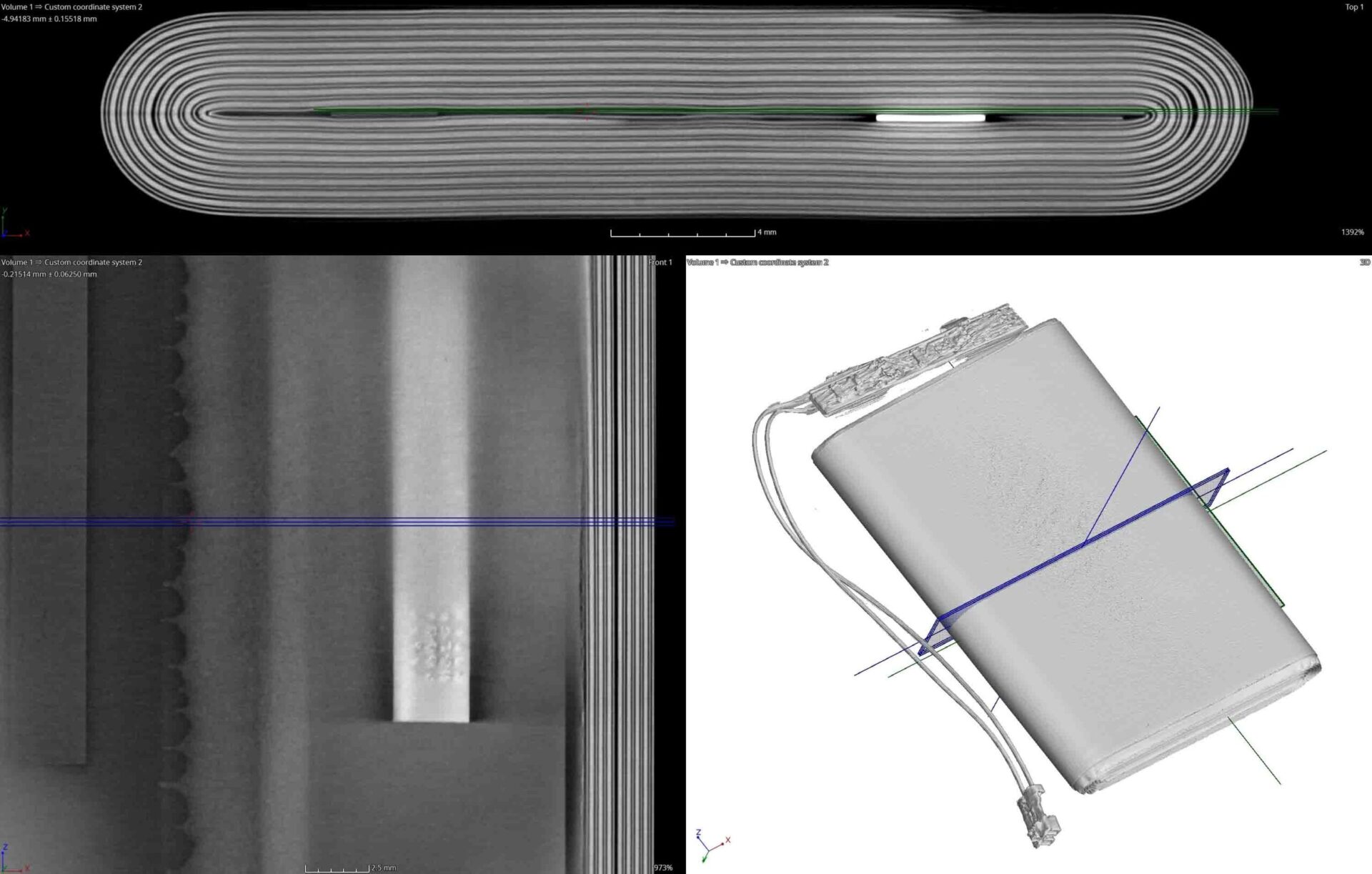
Traditional inspection methods often fall short when it comes to assessing the intricate internal structure of battery cells. However, CT scanning changes the game by providing a non-destructive and highly detailed examination of each cell. With its ability to penetrate solid materials and generate 3D images of internal features, CT scanning offers a comprehensive view of battery cell health.
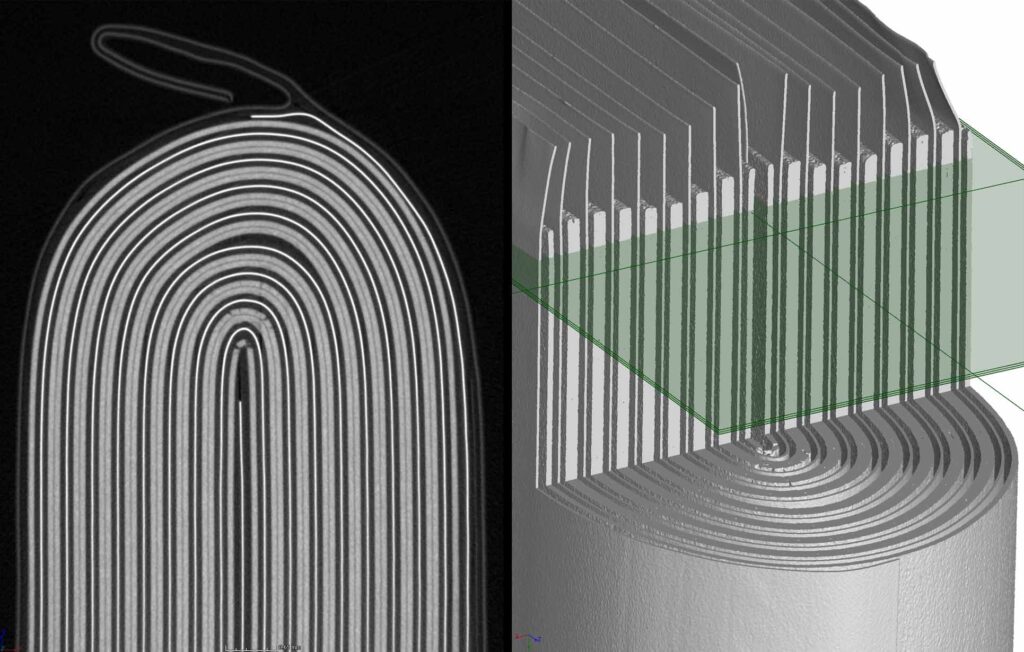
LOOKING FOR DEFECTS
When it comes to ensuring the safety and reliability of battery cells, detecting defects is paramount, and CT scanning offers an unparalleled solution. By leveraging its capability to penetrate solid materials and produce detailed 3D images of internal structures, CT scanning enables manufacturers to meticulously inspect battery cells for defects such as delamination, voids, cracks, or foreign particles. This non-destructive technique allows for early detection of potential issues, ensuring that only cells meeting stringent quality standards are integrated into electric vehicles or energy storage systems. Ultimately, CT scanning plays a pivotal role in safeguarding product quality, enhancing safety, and advancing the development of clean energy technologies.
SORTING CELLS
CT scanning has emerged as a transformative tool for sorting battery cells with unparalleled precision and efficiency. By harnessing its ability to generate detailed 3D images of internal structures, manufacturers can swiftly identify and categorize battery cells based on various parameters such as size, shape, and internal defects. This level of precision not only streamlines the sorting process but also ensures that each battery cell meets stringent quality standards before integration into electric vehicles or energy storage systems. Ultimately, CT scanning enables manufacturers to optimize production workflows, enhance product quality, and uphold safety standards, thereby driving advancements in clean energy technologies.
This LED housing has failed. It was sent to us to try to locate the point of failure, which is equivalent to finding a needle in a haystack. The point of failure is seen in one of the two images below. Can you spot it before moving to the next section of the post?
point of failure
While porosity calculations are interesting, typically an individual joint has a 20% porosity tolerance which can usually be gauged visually. Porosity is not the failure of this part.
If you look near the yellow arrow you’ll see a vertical, linear indication or fracture in the component. During evaluation the inspector uses multiple viewing directions for each component to find such small points of failure. If this crack were perpendicular to the viewing direction it likely would not have been found.
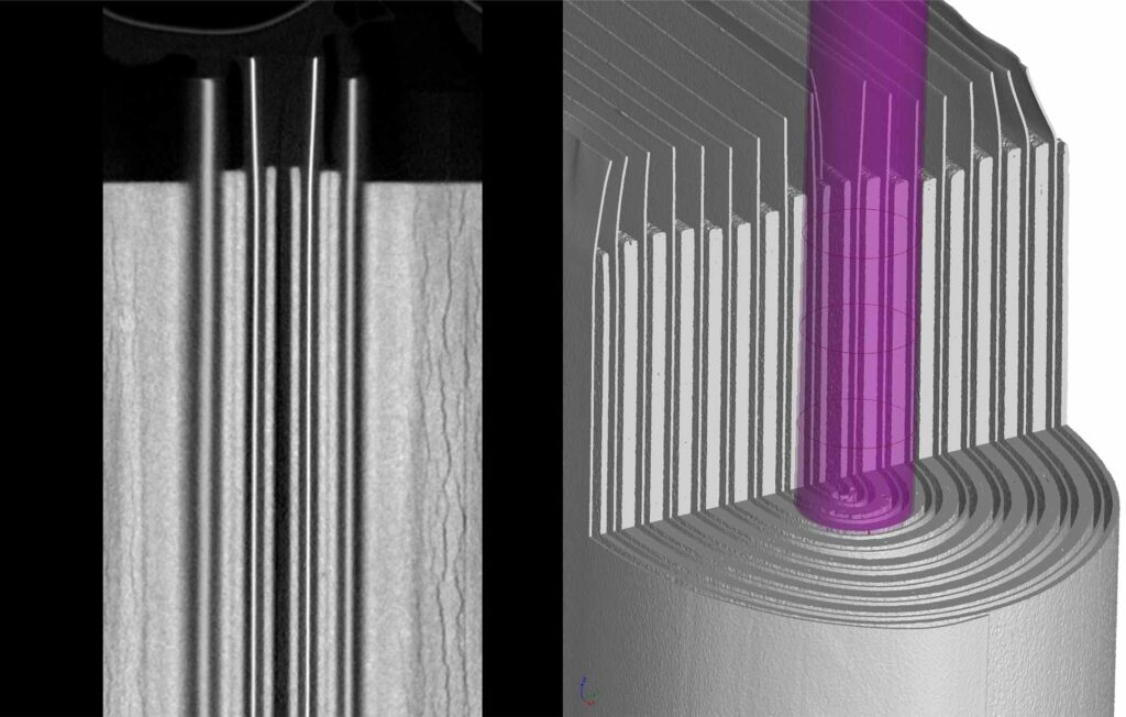
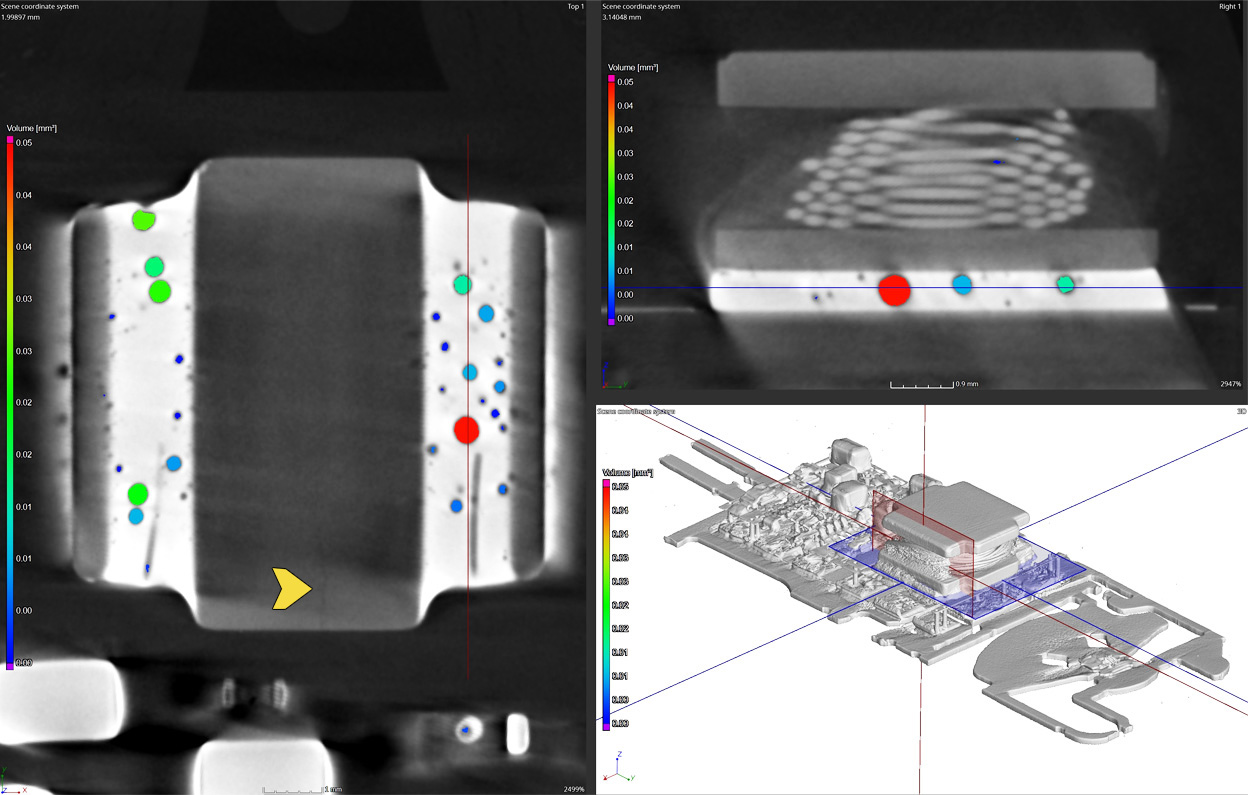
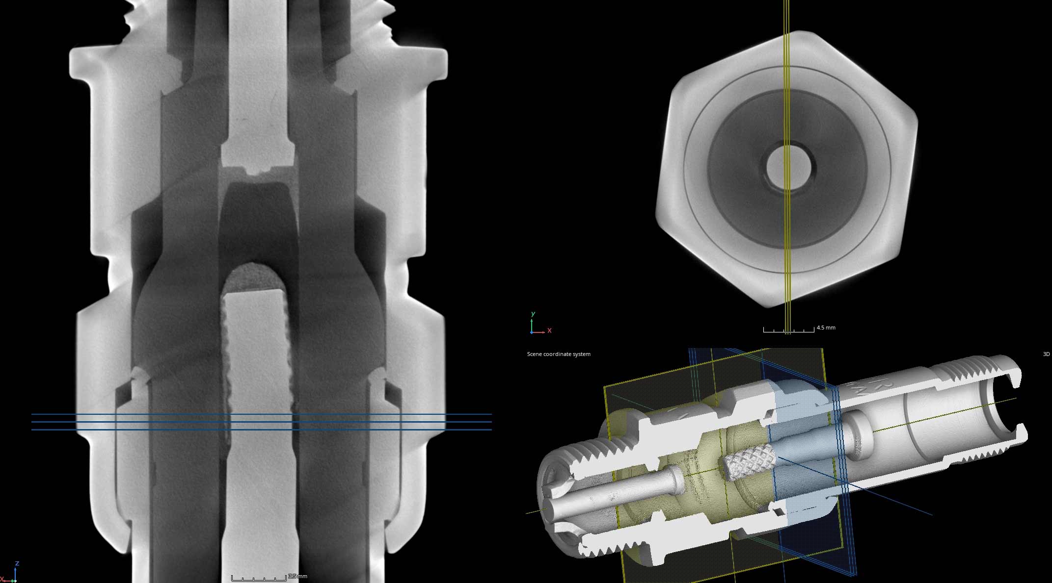
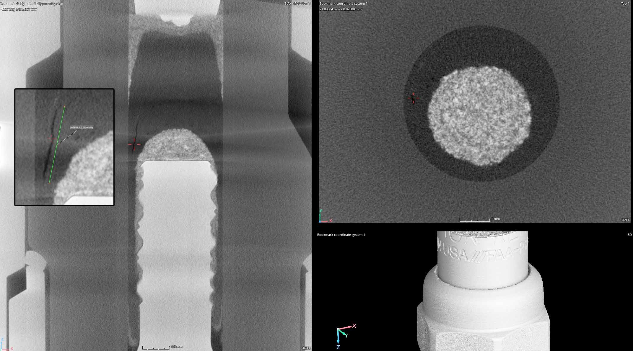
When precision and safety are paramount, the significance of CT scanning for spark plugs cannot be overstated. These small yet vital components play a crucial role in the functioning of aircraft engines, making their integrity and reliability essential. CT scanning offers a non-destructive method to scrutinize these intricate parts, providing engineers with detailed insights into their internal structure and potential defects. By meticulously examining spark plugs through CT scanning, aerospace professionals can identify any anomalies early on, ensuring optimal performance and safety of aircraft engines. Thus, integrating CT scanning into aerospace spark plug inspection protocols not only enhances reliability but also reinforces the commitment to air travel safety.
The below image is a focus scan with improved resolution allowing us to characterize fine details like voids and gaps in the insulation and cracks in aluminum oxide.
FAILURE INVESTIGATION OF HUMAN SUPPORT SYSTEM (CHAIR)
Have you fallen and can’t get up?
Are you struggling to return something to Amazon?
Are you tired of finding 3500mm cubed voids in your products?
Do you wonder why everything is more expensive but doesn’t last as long?
Us too.
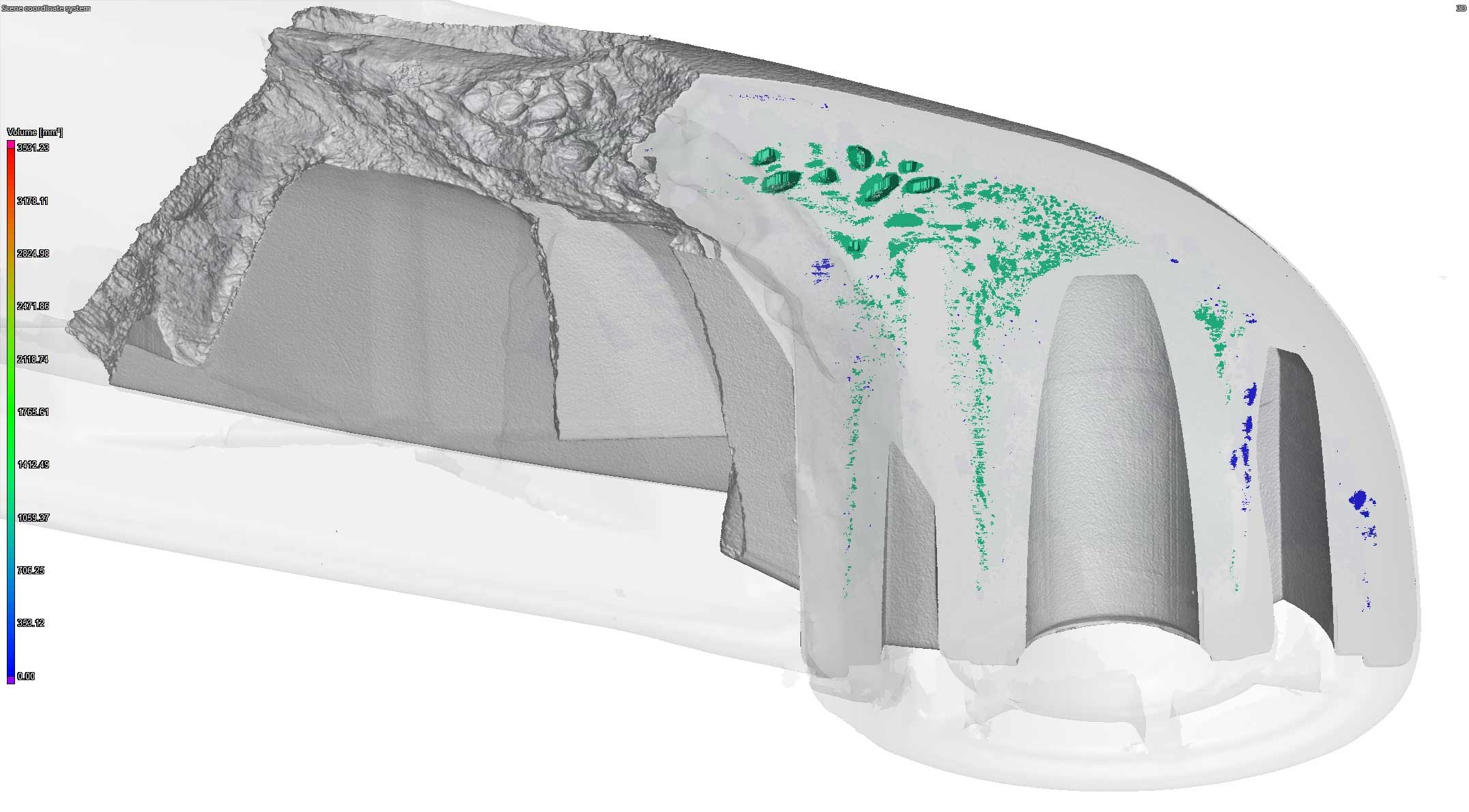
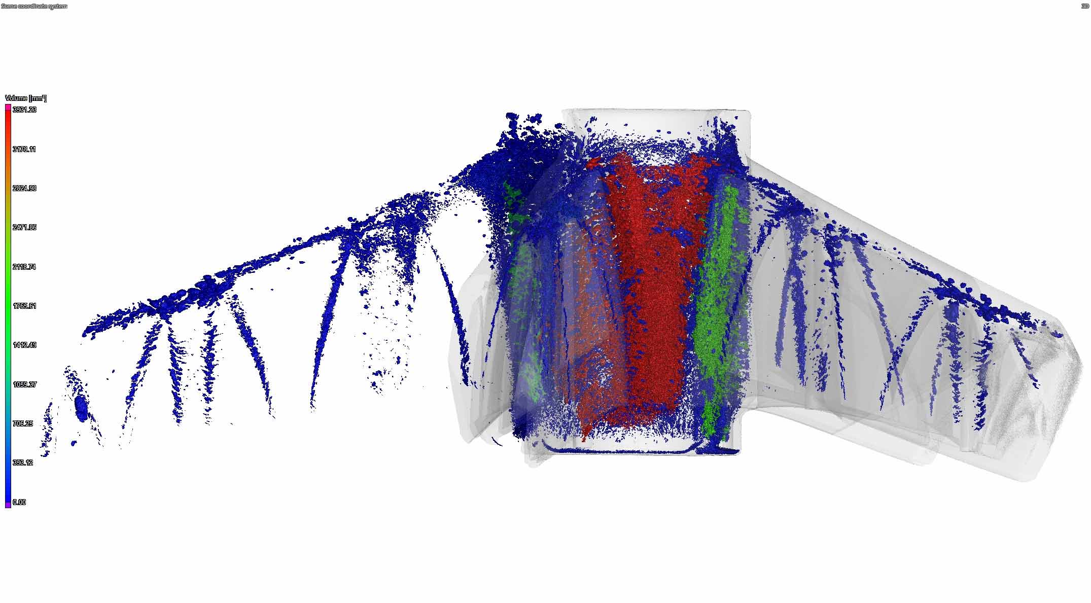
This case study explores the failure of a human support system (chair.)
Industrial CT Scanning is a powerful non-destructive imaging technique used to inspect the internal structure of objects. When applied to plastics to detect porosity, CT scanning provides detailed cross-sectional and 3D rendered images revealing the distribution, size, and shape of voids or pores within the material.
Everyone from manufacturers to law firms have used our services to assist with their fact finding, point of origin, or root cause evaluations.
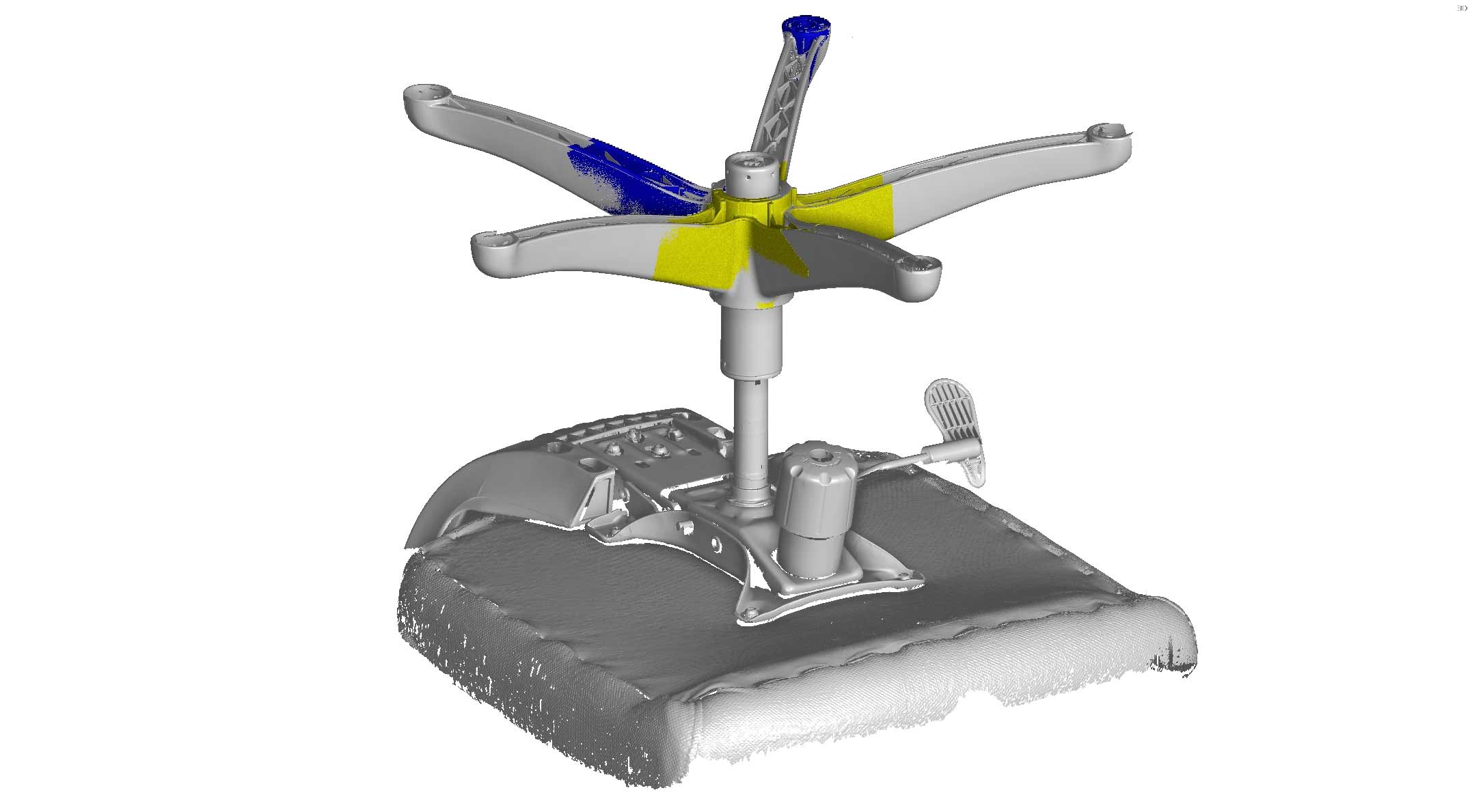
We combine many hardware and software capabilities for the best possible evaluation of products. Because of the size of the chair we used a high accuracy laser scanner (Hexagon Absolute AS1) to capture the overall geometry of a still intact chair. We then created a coordinate system and aligned additional scans of the broken pieces in PolyWorks.
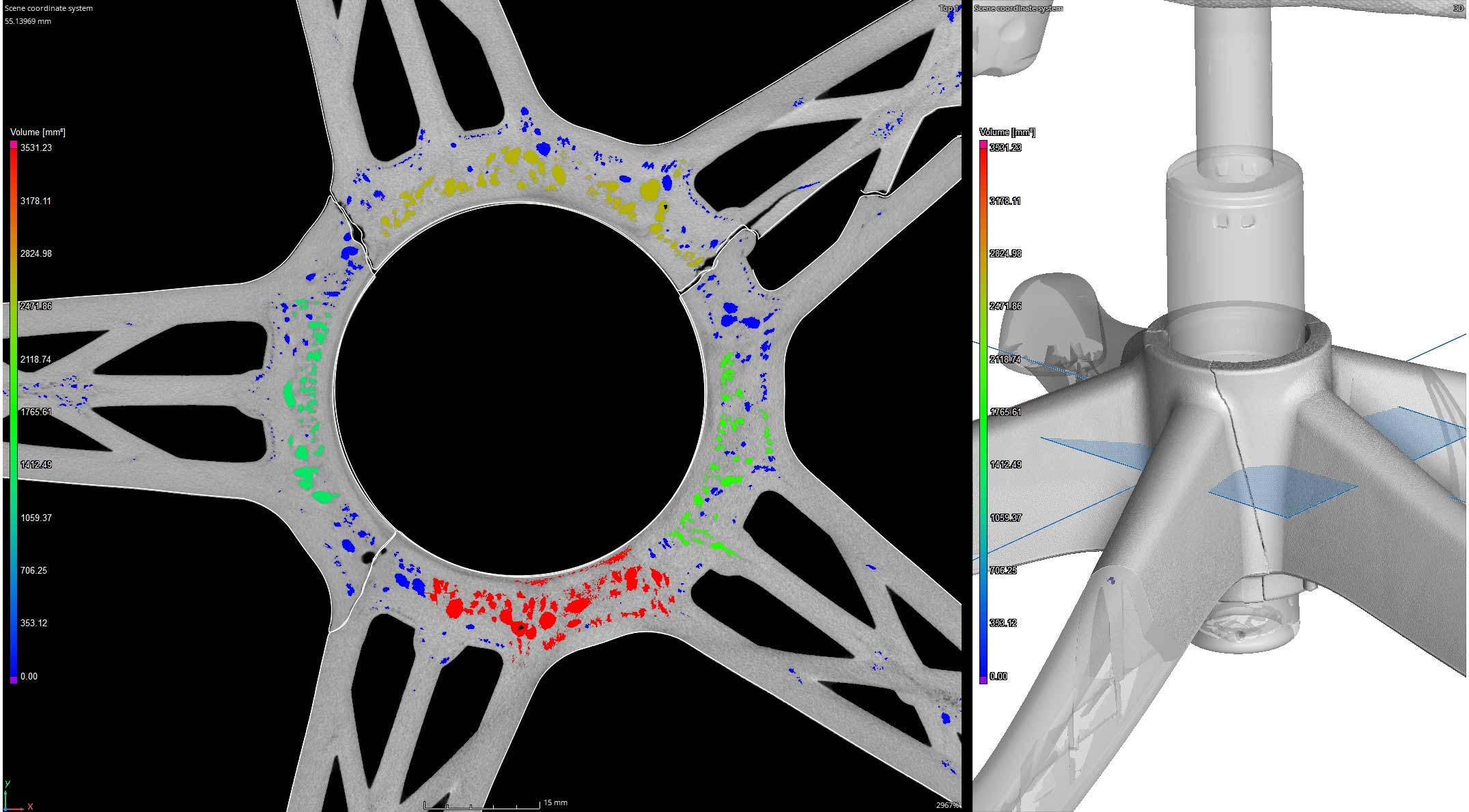
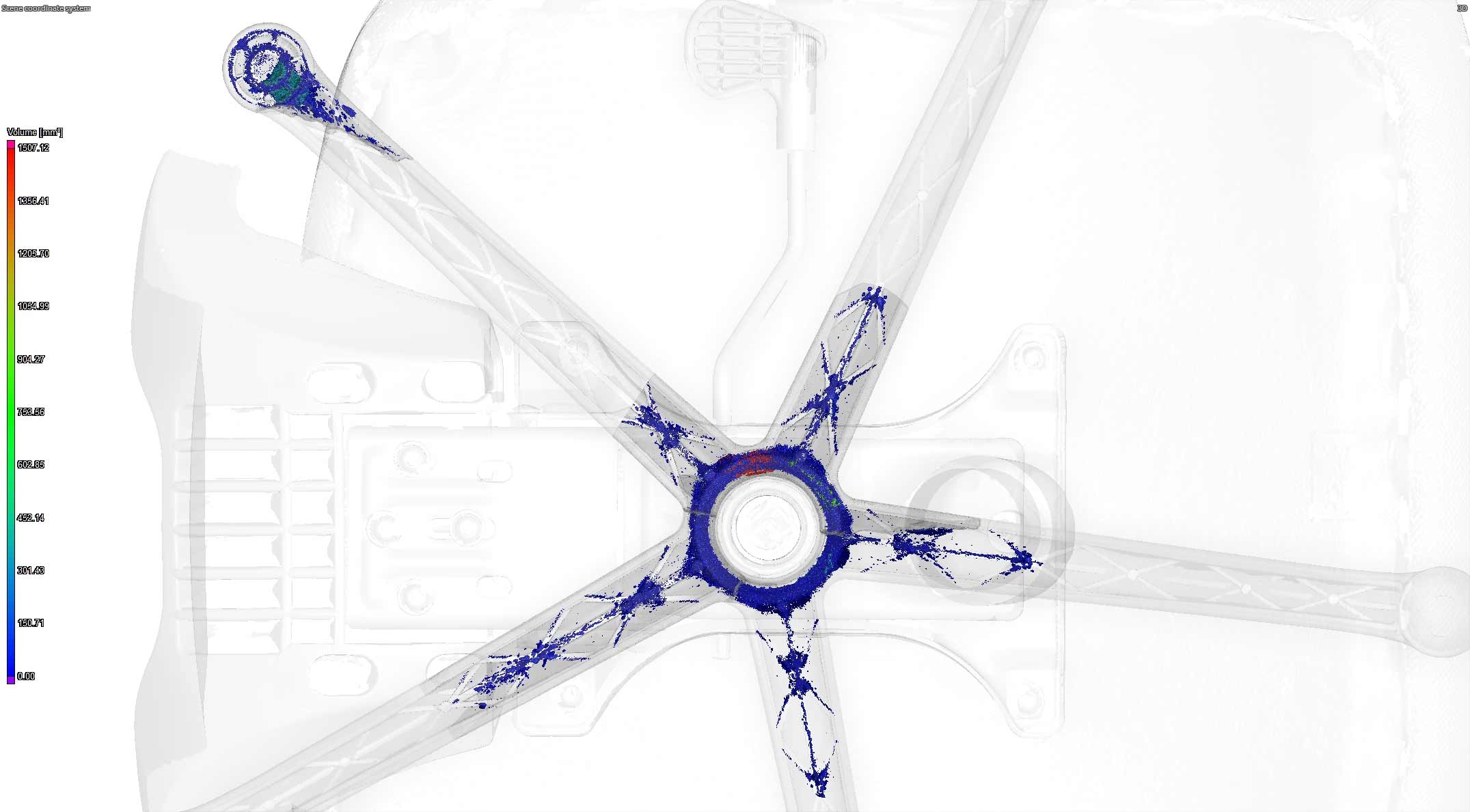
Once everything was aligned properly we imported the .STL mesh files into Volume Graphics to begin aligning the individual CT scans. The CT scans were acquired using our Nikon Microfocus X-Ray & CT cabinet. After the alignments were complete we extracted the volumetric porosity to find voids and cavitation as large as 3500mm3 and found a significant concentration at the base of the chair.
DESIGNING NEW COMPONENTS FOR PERFECT FIT AND FUNCTION
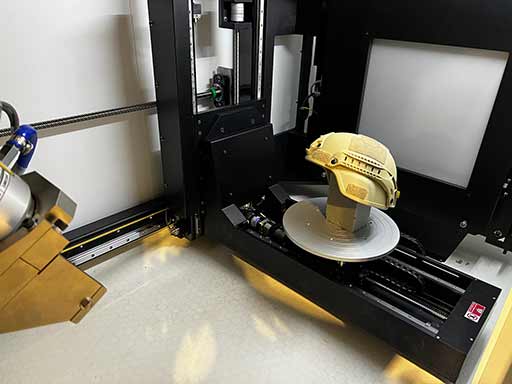
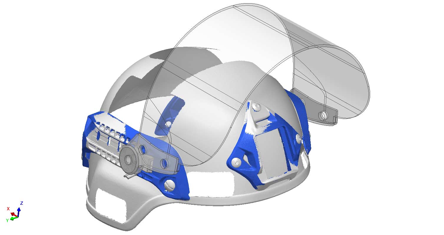
Combining the power of the world’s best scanning hardware and software allows us to produce models with incredible accuracy. This case study focuses on acquiring high resolution, water tight geometry using laser and CT scanning technologies.
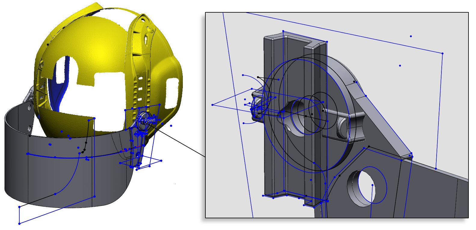
This helmet has several components with attachment features for accessories like lights, visors, and earmuffs. However, if you don’t have existing CAD, how do you effectively design new products?
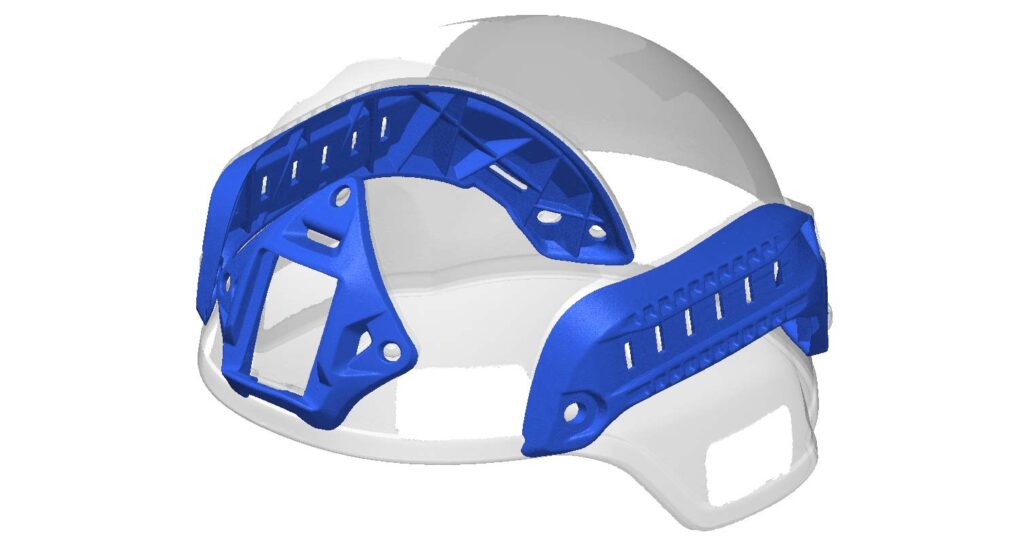
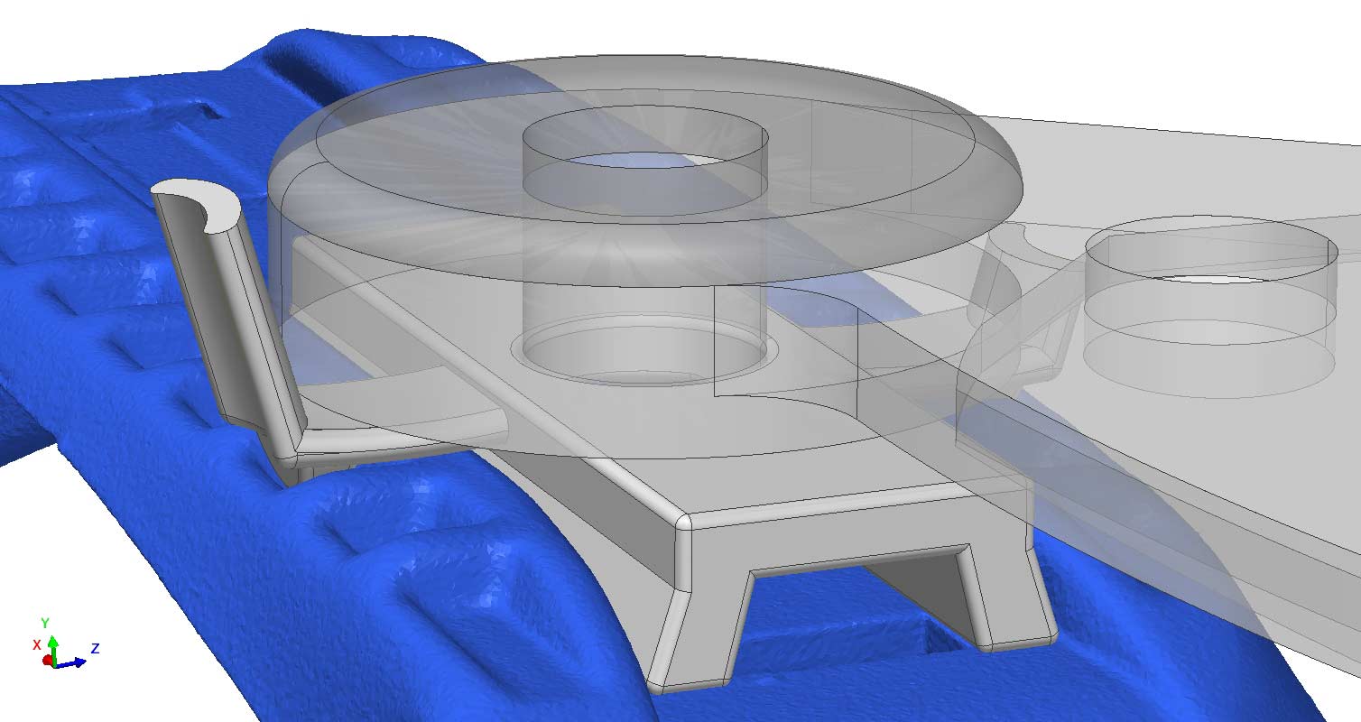
The first step is to acquire water tight, high resolution data. Water tight data means no data is missing in the file. This is important for properly designing a product around all scenarios – if data is missing, you can’t understand proper fit and function. We scanned and segmented the attachment points and built a coordinate system to begin modeling visor attachment mechanisms.
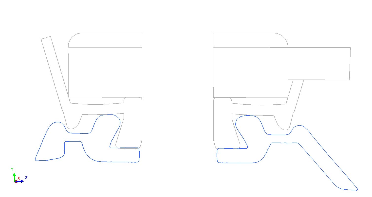
Below shows the 2D sketches produced in Geomagic.
The final step of any reverse engineering project is to verify accuracy of the produced model. This verification takes the form of either Scan to CAD profile comparisons, or visual checks with 2D cross sections. The visor slides fit inside the tracks and the clips have curved tensioners to ensure tight fits into the slots.
Industrial X-ray services are the unsung heroes of modern manufacturing, providing invaluable insights into the inner workings of complex components and materials. From aerospace to automotive industries, these services utilize X-ray technology to peer beneath the surface, uncovering defects, assessing structural integrity, and ensuring product quality with unparalleled precision.
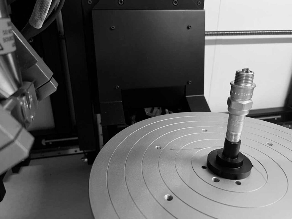
THE HARDWARE
At the heart of industrial X-ray services lies advanced imaging technology that enables the creation of detailed, high-resolution images of objects’ internal structures. This non-destructive testing method allows manufacturers to scrutinize components without compromising their integrity, saving time and resources while maintaining product reliability.
1. X-Ray Source, 2. Part Manipulator, 3. X-Ray Detector
Whether it’s inspecting welds for cracks, detecting voids in castings, or analyzing composite materials for delamination, industrial X-ray services offer a versatile solution for a wide range of applications. With customizable inspection protocols and state-of-the-art equipment, these services can adapt to the unique needs of various industries, providing tailored solutions for quality assurance and defect analysis.
Moreover, industrial X-ray services play a crucial role in ensuring regulatory compliance, particularly in safety-critical industries where the integrity of components is paramount. By leveraging X-ray technology, manufacturers can uphold the highest standards of quality and safety, mitigating risks and enhancing customer trust.
In conclusion, industrial X-ray services represent a cornerstone of modern manufacturing, offering a glimpse into the hidden world of materials and components. With their ability to uncover defects, assess structural integrity, and ensure compliance, these services empower manufacturers to deliver products of uncompromising quality, driving innovation and excellence across industries.
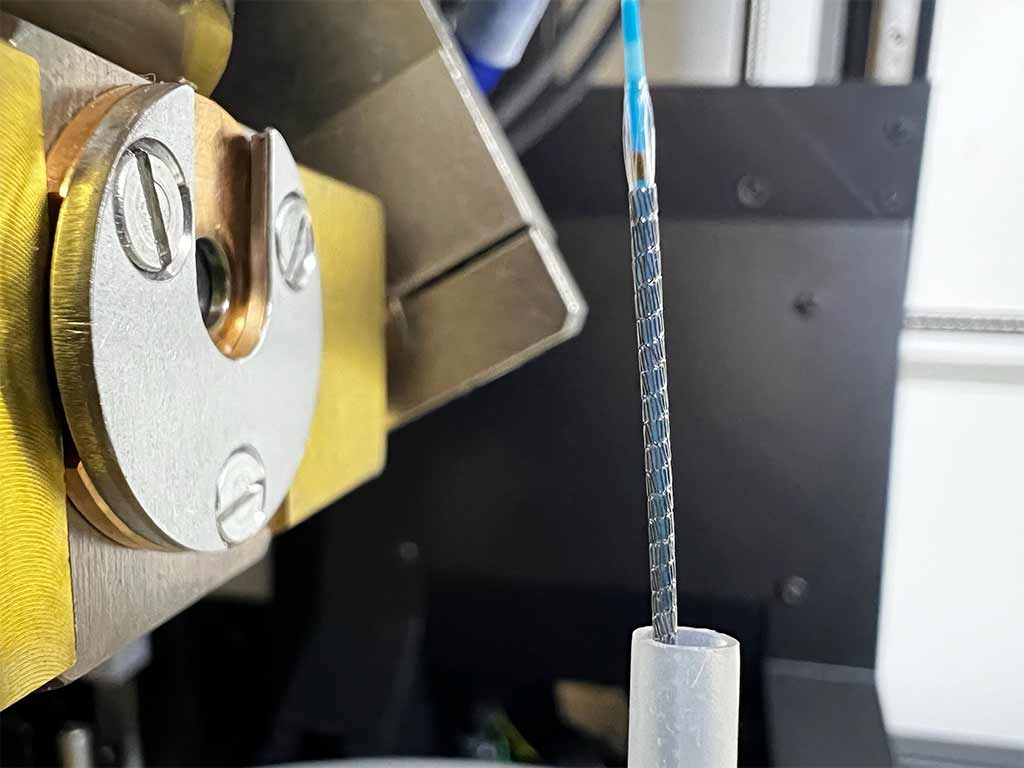
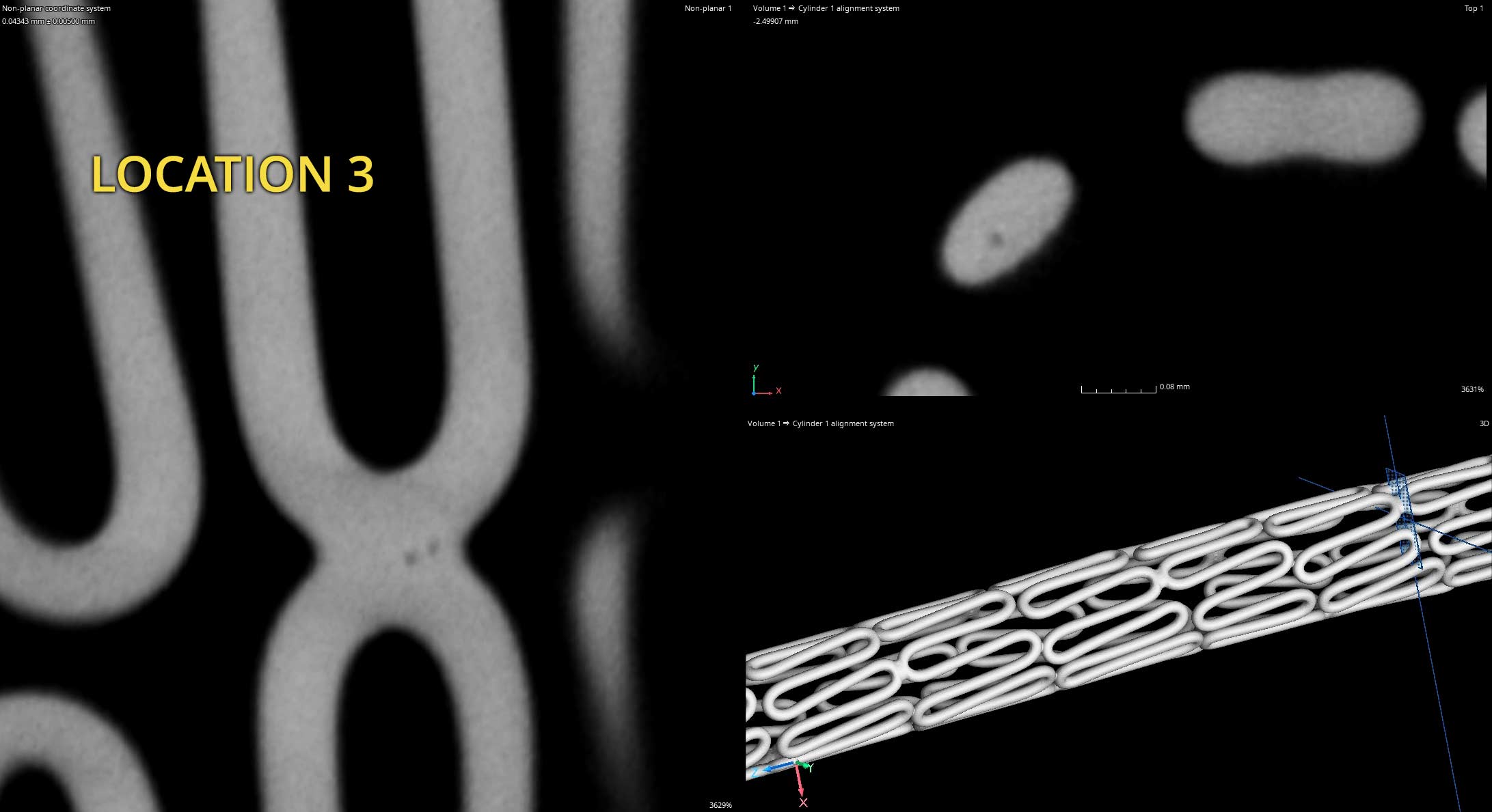
Coronary stents are a specific type of stent used in the treatment of coronary artery disease. These stents are implanted into the coronary arteries, which are the blood vessels that supply oxygen-rich blood to the heart muscle. Coronary artery disease occurs when these arteries become narrowed or blocked due to the buildup of plaque, which is made up of cholesterol, fat, and other substances.
Weld quality directly impacts the safety, efficacy, and longevity of coronary stents. Ensuring high-quality welds is essential for the successful treatment of coronary artery disease and the overall well-being of patients undergoing stent implantation.
Coronary stents often have welds as part of their construction. These welds serve several important purposes:
Joining Components: Stents are typically made from thin metal tubes or wire mesh. Welding is used to join these components together to form the desired stent structure. The welds ensure that the stent maintains its shape and structural integrity during deployment and once it’s in place within the artery.
Sealing Edges: Welding can be used to seal the edges of the metal components, preventing them from unraveling or causing damage to the artery walls during insertion or deployment. This sealing helps to ensure the safety and effectiveness of the stent.
Reducing Material Weakness: Welding is often employed at points where different parts of the stent meet. These junctions can be weak spots if not properly reinforced, and welding helps to strengthen these areas, reducing the risk of failure or breakage.
Smooth Surface: Welding can be used to create smooth transitions between different sections of the stent, which can help to minimize irritation to the artery walls and reduce the risk of complications such as clot formation or restenosis (re-narrowing of the artery).
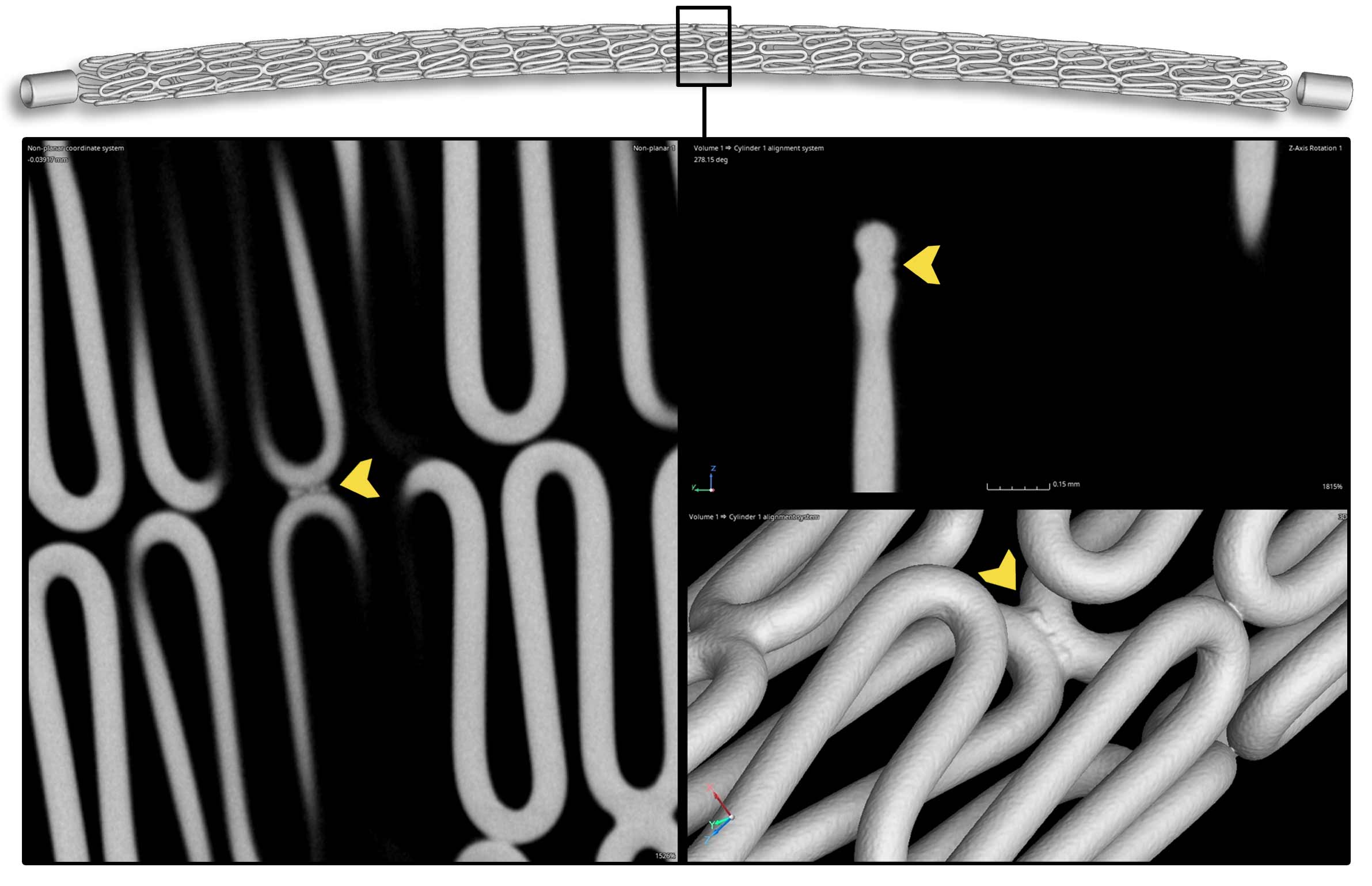
POROSITY IN STENT WELDS
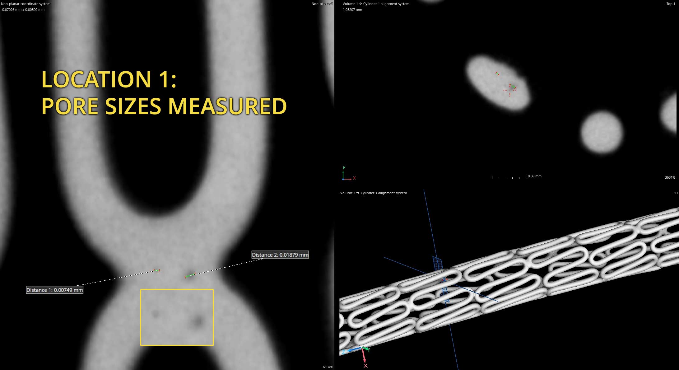
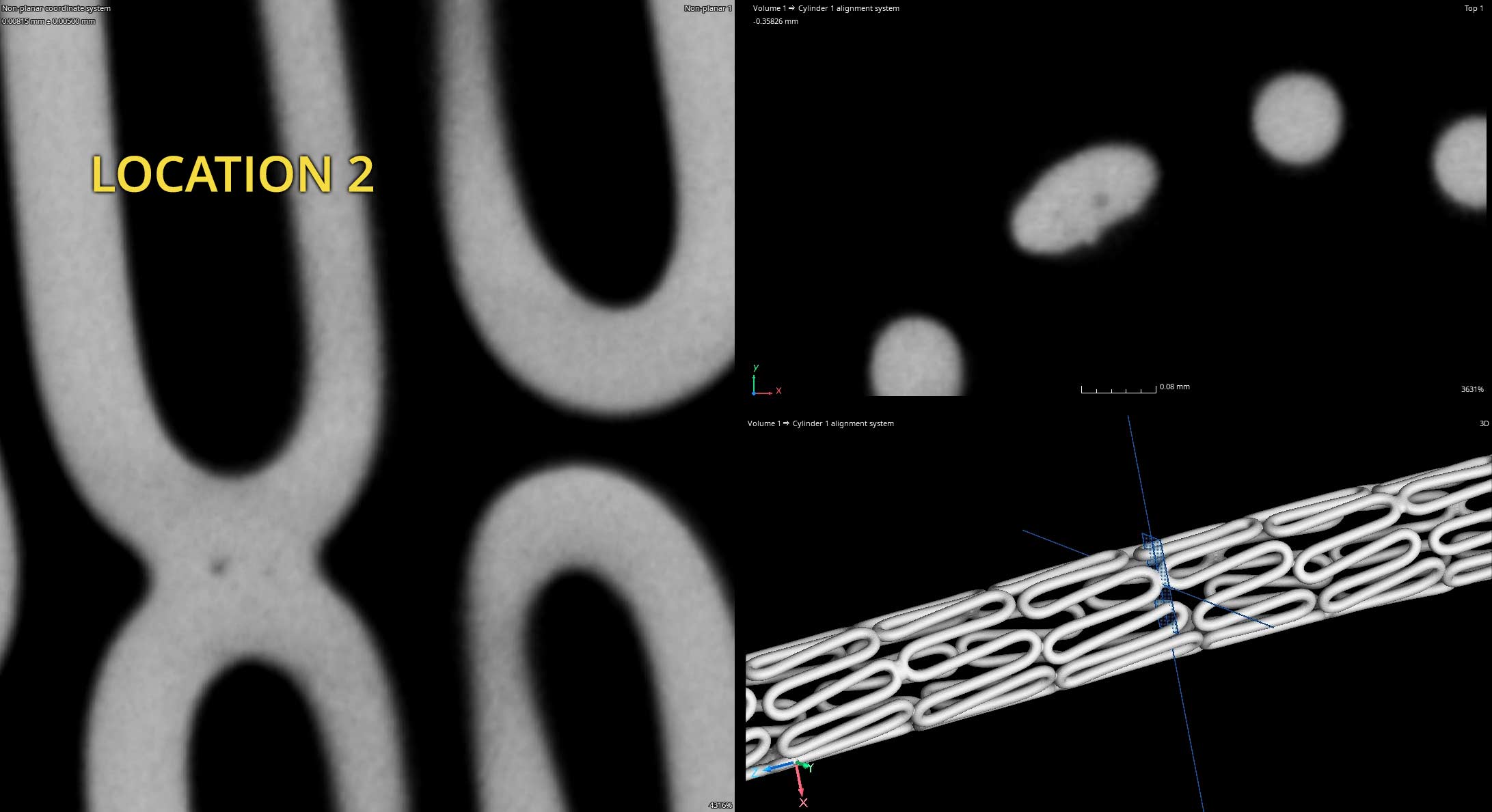
Porosity in stent welds refers to the presence of small voids or air pockets within the welded region of the stent. This porosity can occur due to various factors during the welding process and can have significant implications for the quality and performance of the stent. Here are some key points regarding porosity in stent welds:
Reduced Mechanical Strength: Porosity weakens the welds, making them more prone to cracking, fracturing, or deformation under mechanical stress. This compromises the structural integrity of the stent and can lead to premature failure or breakage during deployment or while in place within the artery.
Increased Risk of Corrosion: Porous welds create pathways for corrosive agents, such as bodily fluids or environmental factors, to penetrate the stent material. This can accelerate corrosion processes, leading to degradation of the stent over time. Corrosion weakens the material and can result in structural failure, particularly in environments with high levels of oxidative stress.
Poor Biocompatibility: Porous welds may have rough or irregular surfaces, which can increase the risk of tissue irritation, inflammation, or thrombosis (blood clot formation) when the stent is implanted in the body. The presence of voids or air pockets within the welds can also serve as sites for bacterial adhesion, raising the risk of infection at the implantation site.
Compromised Drug Delivery (for Drug-Eluting Stents): In drug-eluting stents, where medications are coated onto the stent surface to prevent restenosis, porosity in the welds can affect the uniformity and integrity of the drug coating. This may result in uneven drug release or premature degradation of the drug layer, reducing the efficacy of the stent in preventing re-narrowing of the artery.
Difficulty in Inspection and Quality Control: Porosity in welds can be challenging to detect visually or with conventional inspection methods. This makes it difficult to ensure the quality and reliability of the stents during manufacturing. Advanced non-destructive testing techniques, such as X-ray and CT Scanning, may be required to identify and quantify porosity accurately.
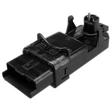
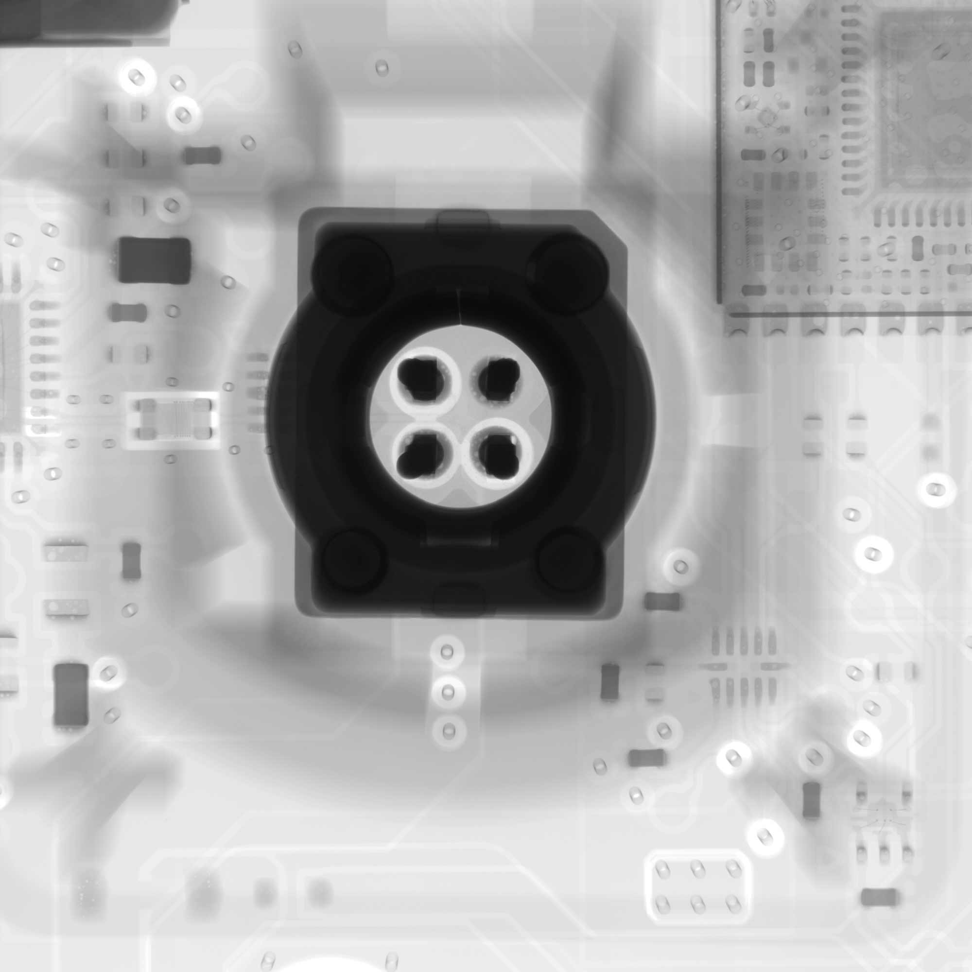
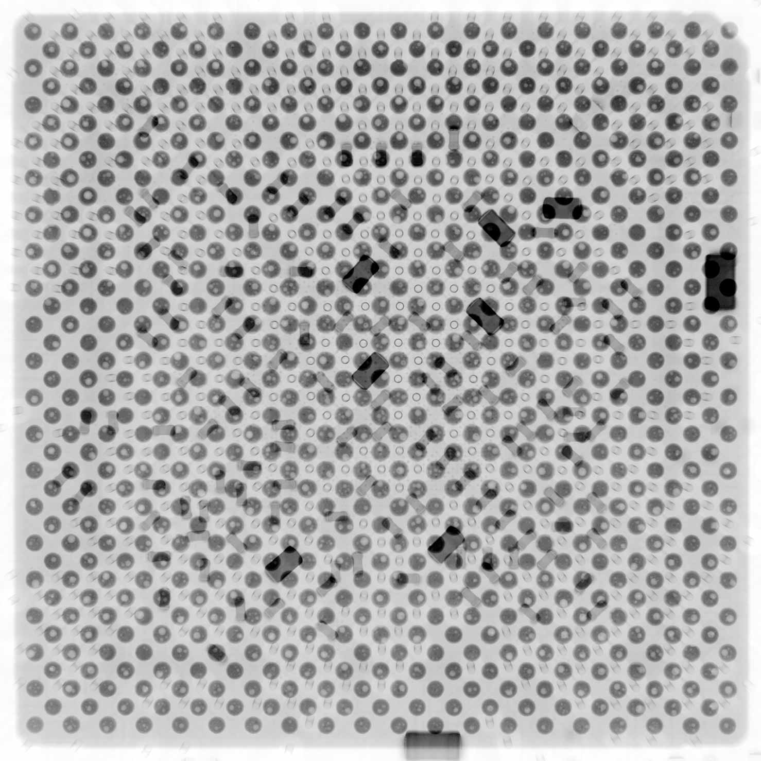
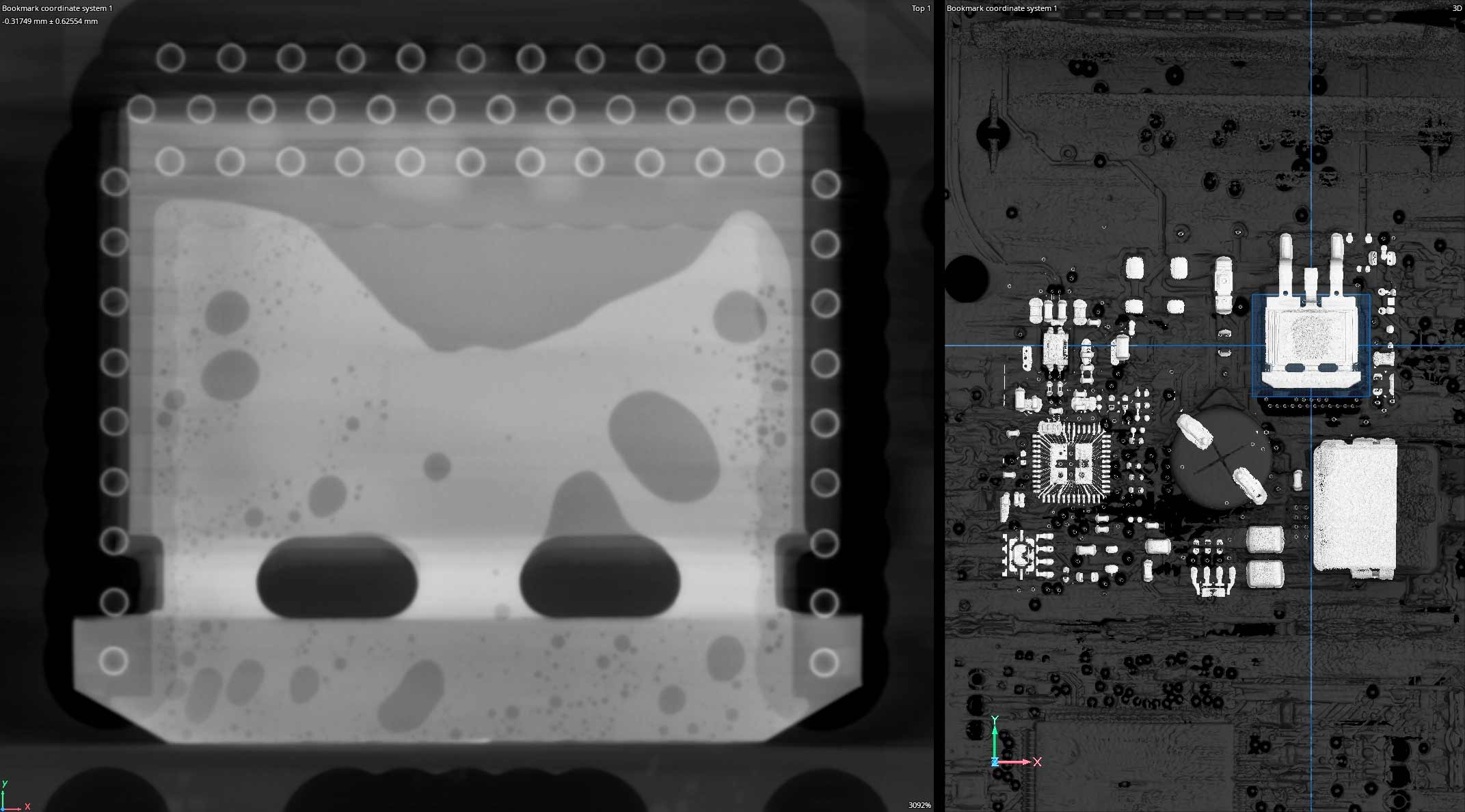
Industrial X-Ray & CT scanning is used to non-destructively evaluate printed circuit boards.
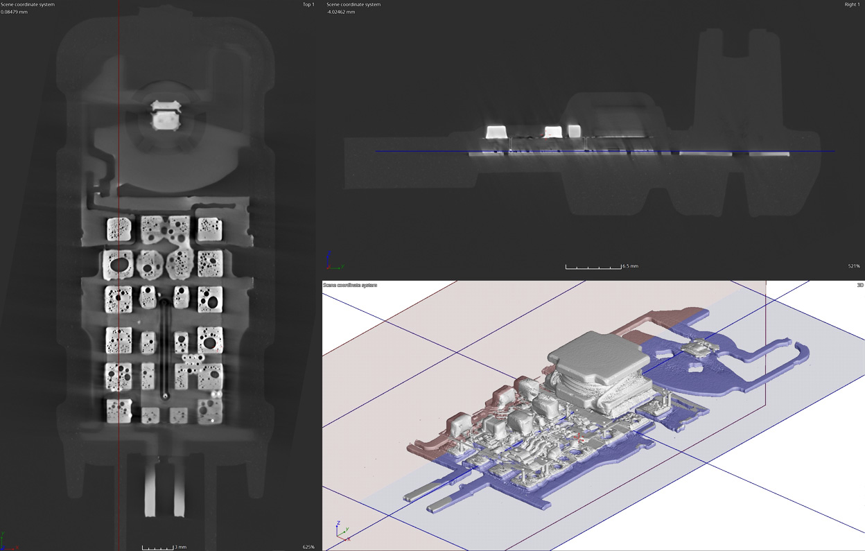
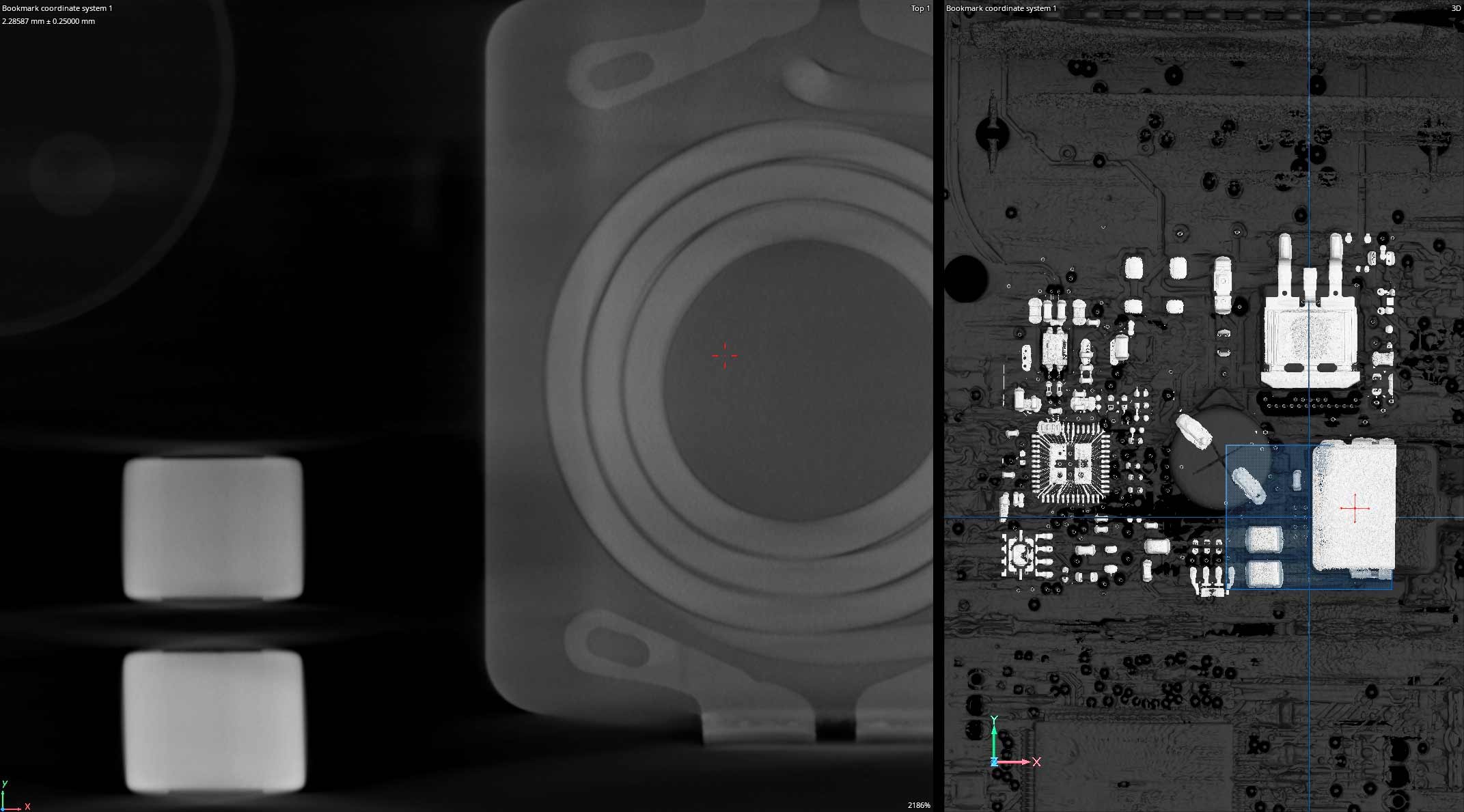
2D X-RAY
2D x-ray allows our certified technicians to quickly inspect features like bond wire straightness, pin perpendiculariy, BGA porosity, trace defects, and capacitor cracks. Our high resolution systems are fully programmable allowing automated image acquisition including translations, rotations, and magnification changes.
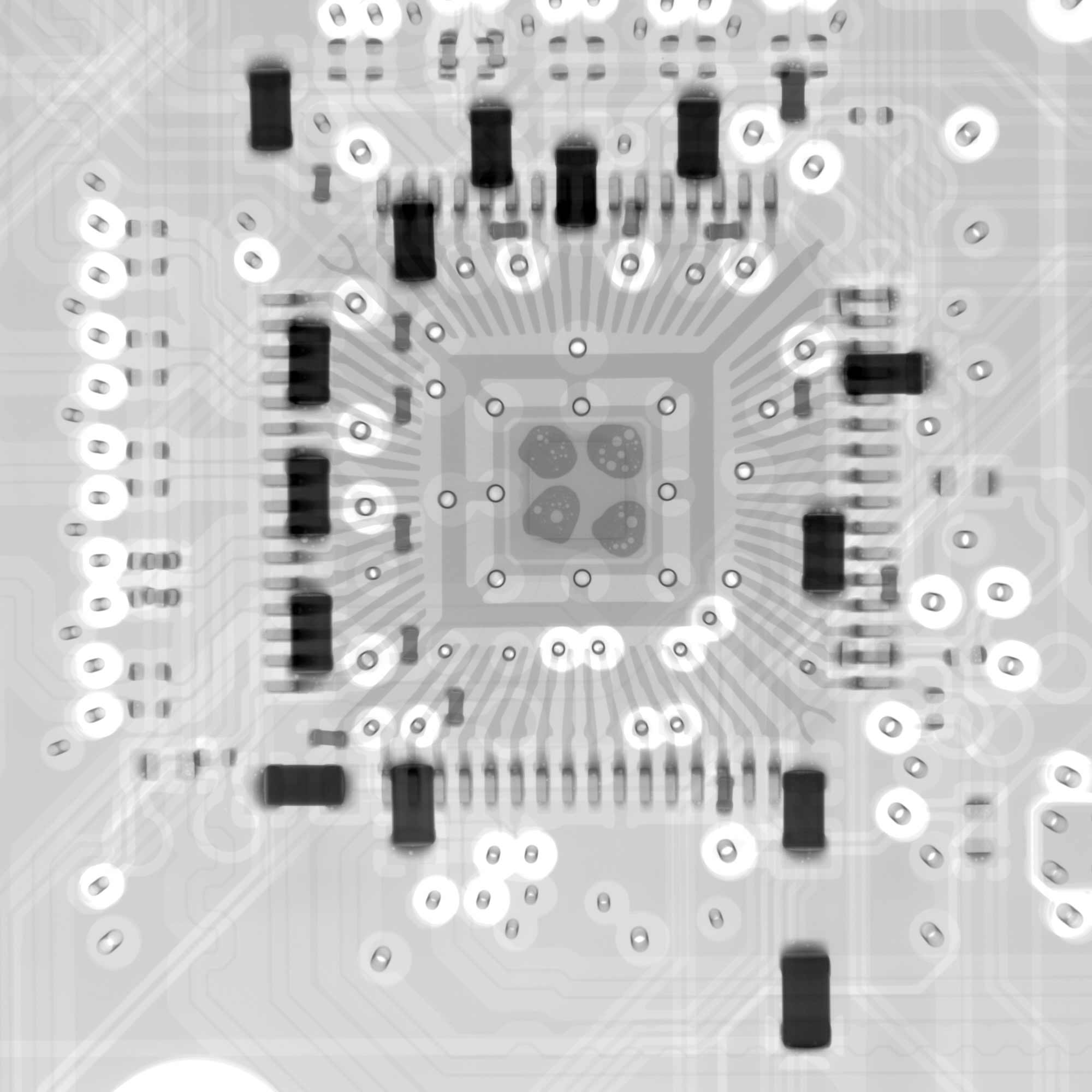
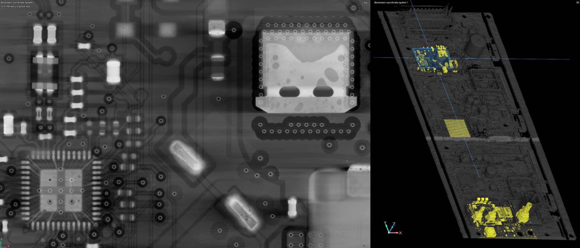
3D CT SCANNING
3D CT scanning offers an additional viewing axis for inspection. With 2D X-Ray all geometry in the view is viewed simultaneously. With 3D CT we can navigate through a tangible inspection volume where a larger variety of digital tools are available. For example, precise component alignments can be created. Additionally, dimensions can be extracted like depth of discontinuities, volumetric porosity, wall thickness, and complex 3D GD&T like flatness or feature positions.
X-RAY IMAGING
CT IMAGING
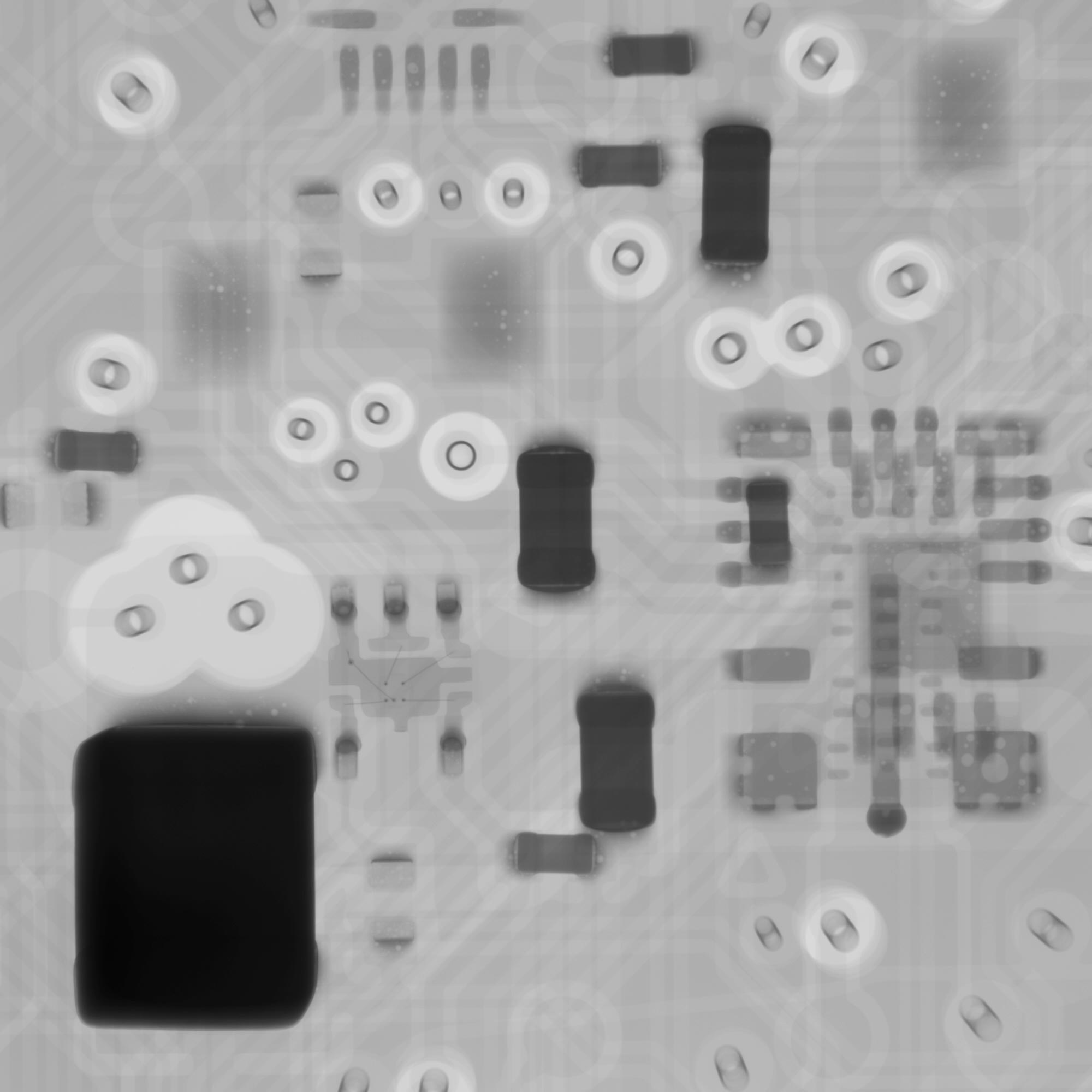
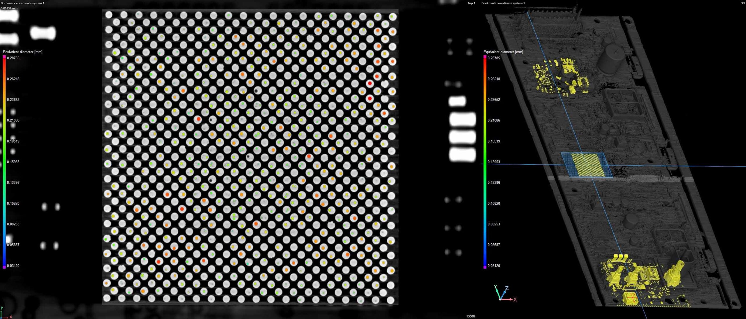
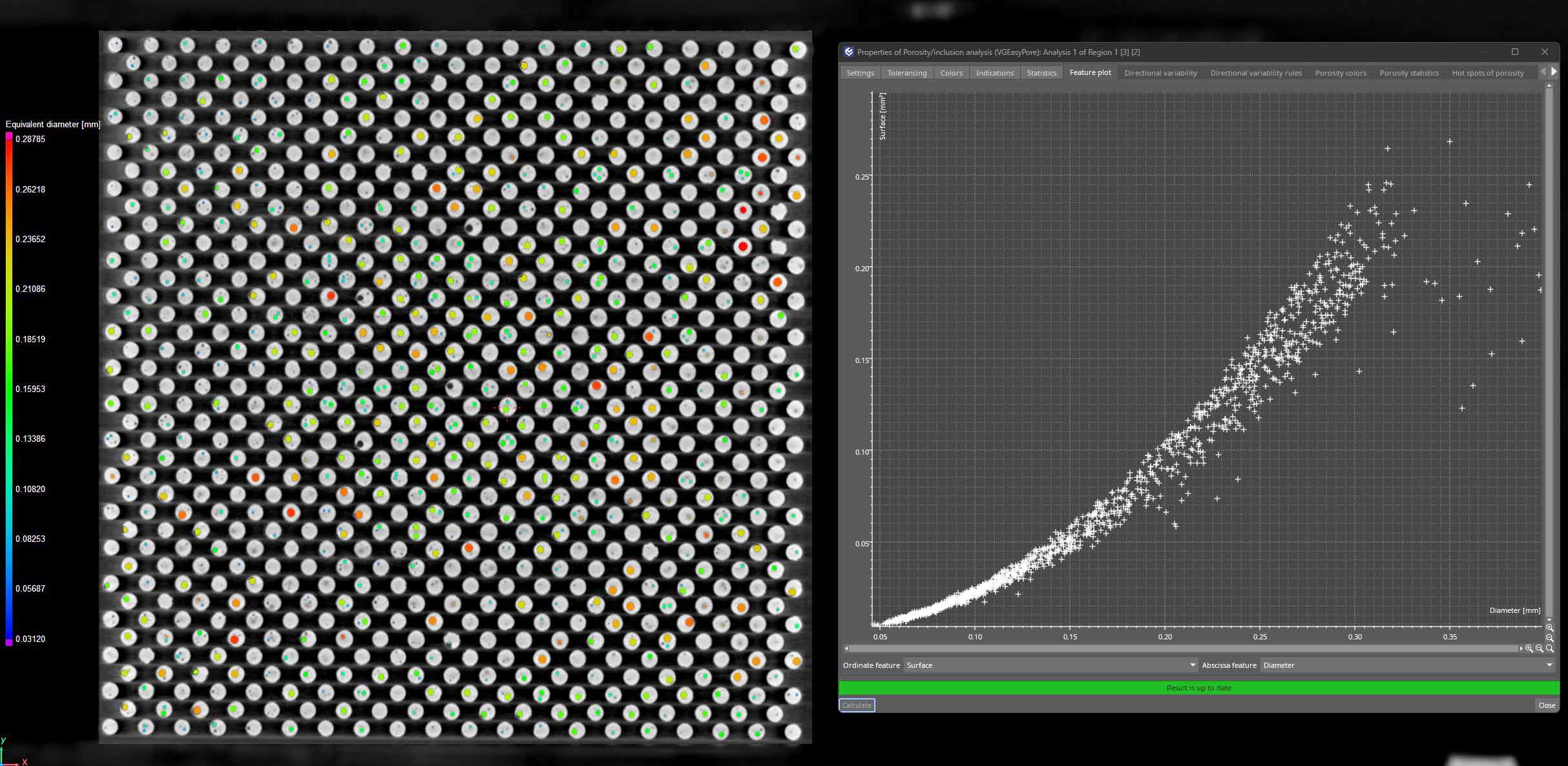
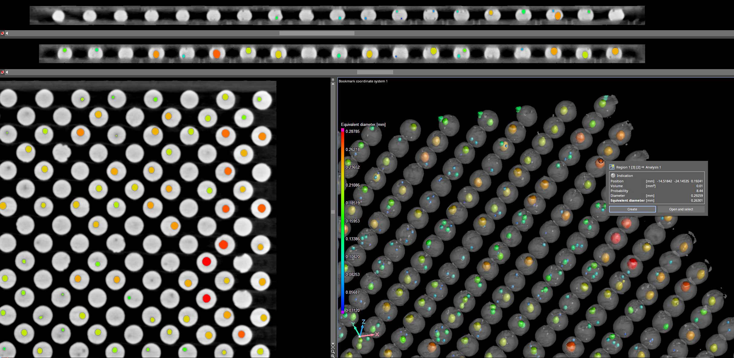
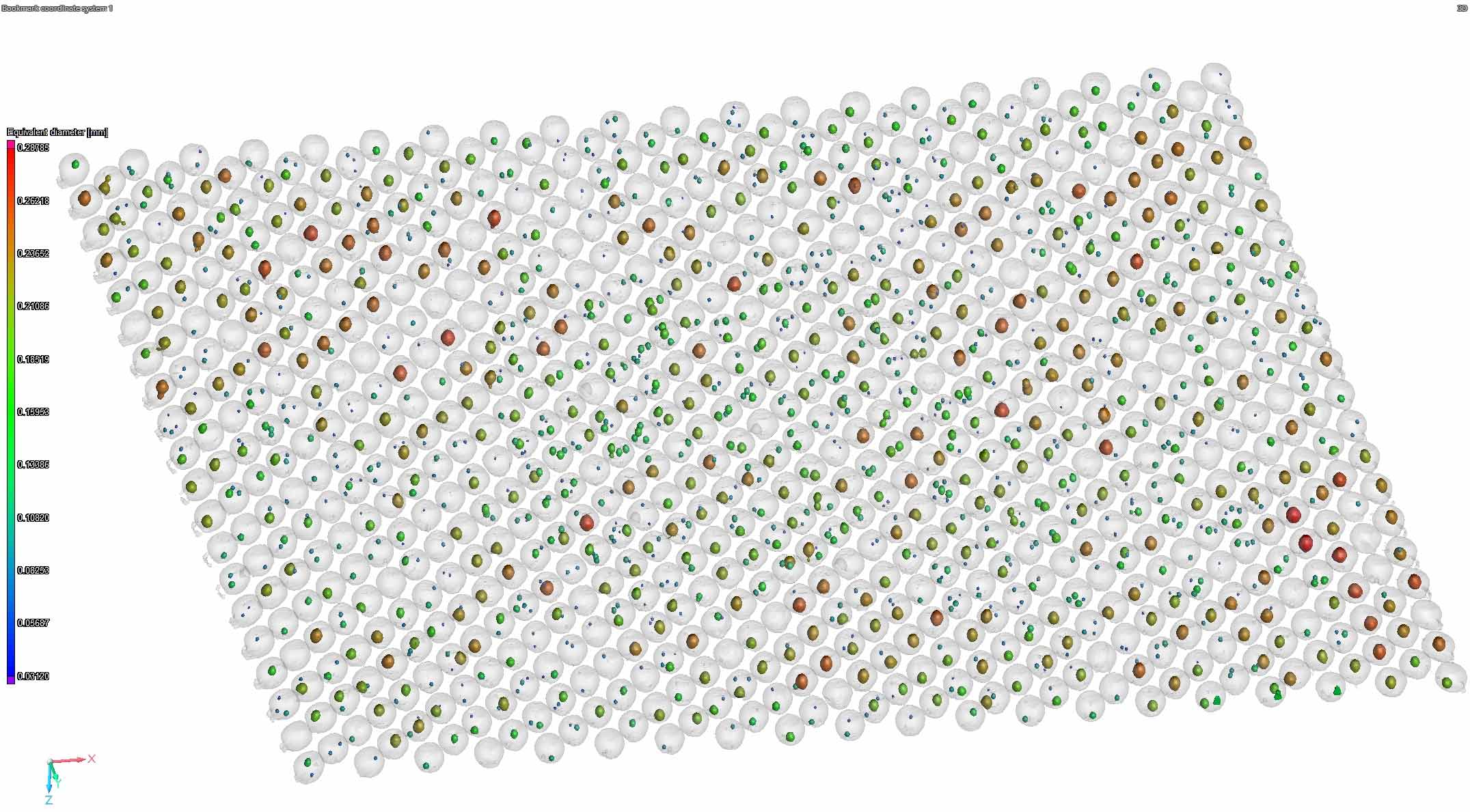
VOLUMETRIC POROSITY & DATA EVALUATION
Porosity can be extracted, volumetrically quantified, and exported into Excel. Such values as total porosity percentage, individual pore volume, equivalent diameter, and XYZ positional data can be produced.
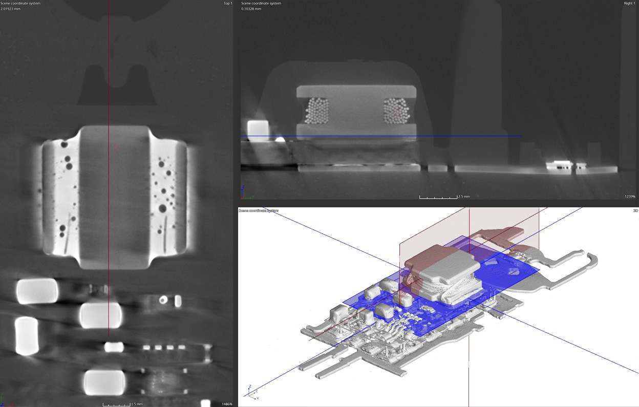
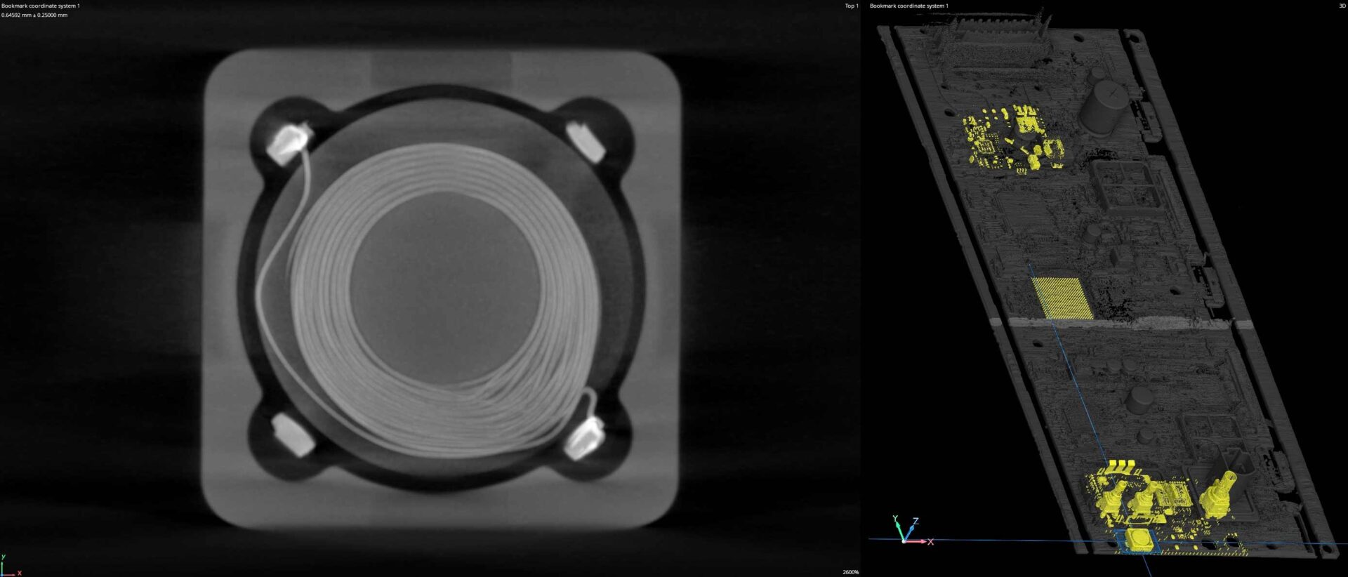
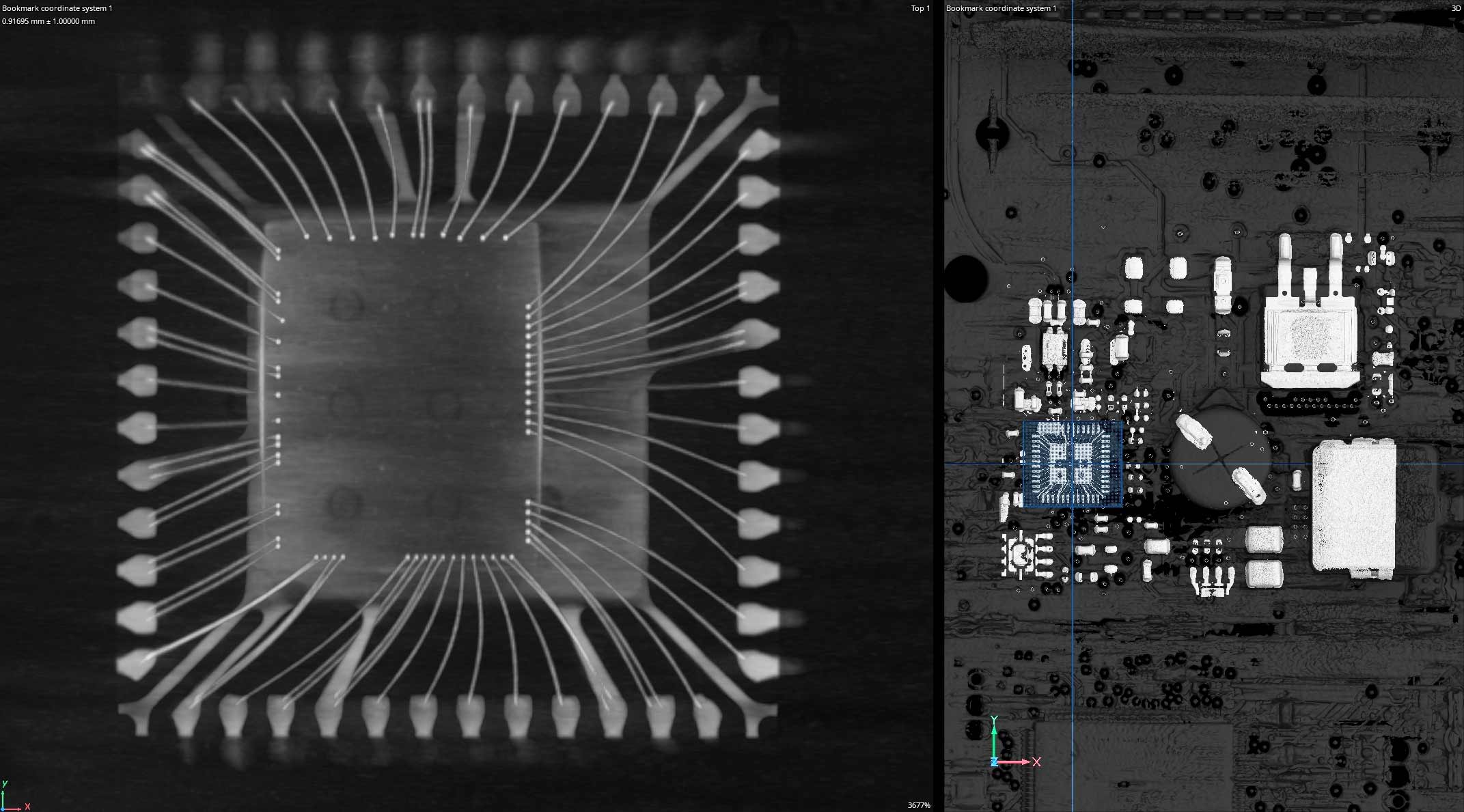
VIEWING FILTERS
Various viewing filters can be applied to the CT slice data. Instead of looking through a single slice of geometry, we can look at the highest density features across a specified length. For example, the bond wires below are imaged using a maximum density filter across a 2mm zone. If data is particularly noisy, an average min/max filter can be applied to help the inspector understand the geometry.