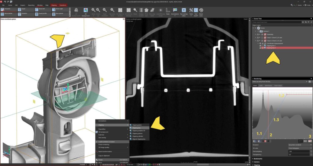
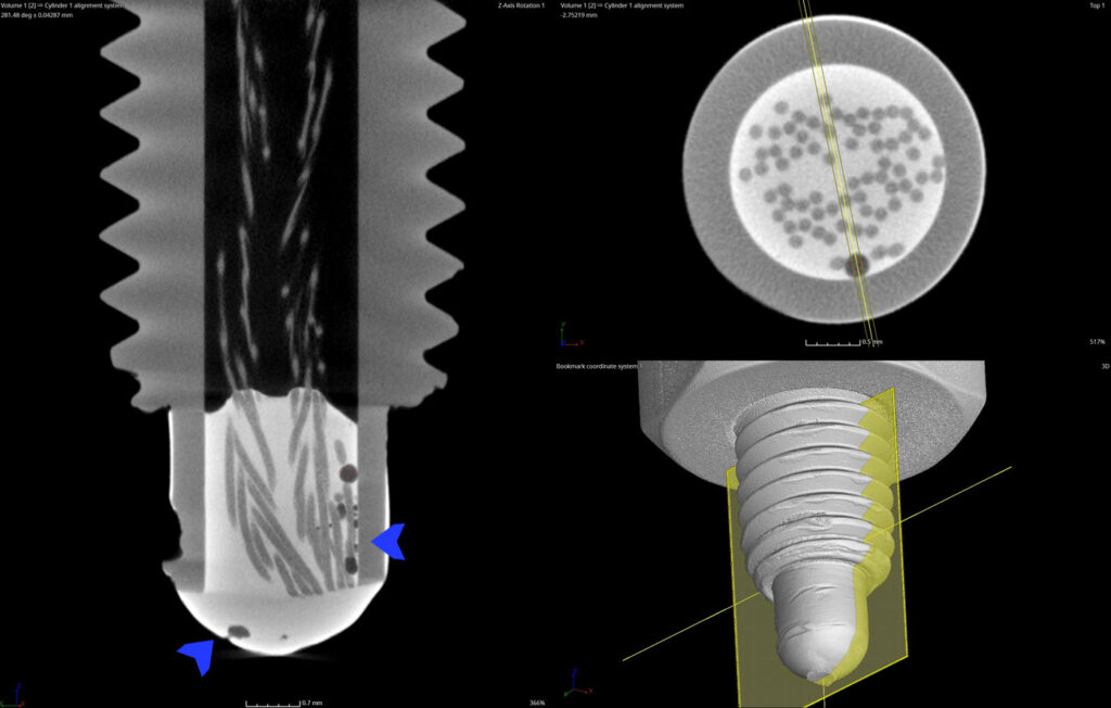
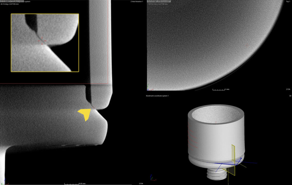
MyVGL Tutorial & Users Guide for CT Analysis

Become a CT Expert using MyVGL

In just a few steps you can become an expert CT analyst. This guide demonstrates the basic, step-by-step functions of the industrial CT industry’s standard software: Volume Graphic’s myVGL Viewer.

1. Download myVGL & Open File

myVGL is the free viewing app for projects created with Volume Graphics Software.

myVGL Download Page

With myVGL, you can view 3D objects (in voxel, point cloud, mesh, and CAD format), the analyses and measurements performed on these objects, and define your own measurements and imaging results!

2. ACTIVATE NECESSARY TOOLS

Navigate to the Window pane. To the right, click the “Tools” drop down to activate important sidebar options like Rendering, Scene Tree, and Bookmarks.

Rendering allows for contrast adjustment, Scene Tree shows the different files and tools within the project, and Bookmarks allow you to navigate between saved images.

3. NAVIGATION

Clicking the cursor navigation button in the upper left corner allows the user to navigate to a single location in all window views simultaneously. Hold Ctrl + Left Click any location.

In the Window menu the viewing panes can be modified or removed for optimal viewing of areas of interest. Quad View is standard which shows all three planar directions and a 3D render view in the bottom right. Additional options include Rotational View about an axis, or Unroll View which planarizes cylindrical features.

4. CONTRAST & RENDER ADJUSTMENT

Adjusting the contrast of the scan data is done in the Rendering window you activate earlier. The Histogram contains a variety of tools including a sliding bar. At the ends of the bar are upper and lower limit handles (1.1 and 1.2). Drag these to adjust the contrast. You can move both handles simultaneously by selecting and dragging 1.3. Location 2 shows the Gray Value rendering slider and Location 3 activites and deactivates the ability to adjust the Gray Value rendering slider.

Right clicking the 3D renderopens a menu with a variety of options including clipping tools. Clipping tools can be used to digitally section the part, and the sections are saved to be activated or deactivated in the upper right Scene Tree.

5. SLICE SETTINGS

Right click any viewing pane to open pane settings menu. Primary viewing tools including:

  1. Thick slab – the slice thickness control which has parameters to define thickness, bring forward the highest density gray values in that thickness, slice averaging, and so on.
  2. Slice step width – how far the viewer scrolls through each tick of the mouse. The small the value, the slower the scroll and more detail will be viewed.

6. MEASUREMENTS

A variety of measurement options are available in myVGL including basic dimensioning like distances, angles, and polylines. However, complex dimensional tools like profiling, wall thickness, CAD alignments, and coordinate systems are reserved for full Volume Graphics Cast & Mold licenses.

Indicators are used to mark areas of interest and recover their locations quickly. Calipers use rendered surface data to create tangible distance measurements.

7. IMAGING & REPORTING

In the Reporting panel measurements can be exported to Excel and images can be exported using the Save Image button. Images can be modified based upon the current state of the defined windows of the software or as defined in the Save Image pane.

2D slice videos can also be exported.

8. METROLOGY USING POLYWORKS

Visit our case study about dimensional inspection of these vacuum heads using PolyWorks Metrology Suite here.

Complex dimensional programs can be written for large batches of parts for GD&T and profile analysis.

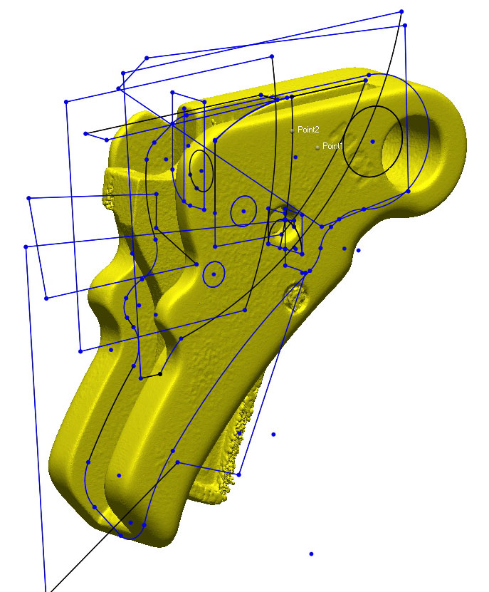
What is Reverse Engineering?

Unlocking Innovation: The Power of 3D Scanning for Reverse Engineering

Innovation is the lifeblood of progress, driving industries forward by leaps and bounds. But what happens when innovation meets the physical world, where existing objects and components stand as formidable barriers to progress? Enter 3D scanning for reverse engineering – a transformative technology that bridges the gap between the physical and digital realms, unlocking a world of possibilities for designers, engineers, and innovators alike.

The Essence of Reverse Engineering

Reverse engineering is the process of deconstructing and understanding the design of a physical object to recreate it digitally. Traditionally, this involved meticulous measurements, manual drawings, and countless hours of labor. However, the advent of 3D scanning has revolutionized this practice, offering a faster, more accurate, and incredibly versatile solution.

Harnessing the Power of 3D Scanning

At the heart of reverse engineering lies 3D scanning technology, which enables the precise capture of an object’s geometry in stunning detail. Using techniques such as laser scanning, structured light scanning, or CT scanning, 3D scanners generate point clouds or mesh models that faithfully replicate the physical form of the object.

REVERSE ENGINEERING WORKFLOW

1. Data Acquisition: The object of interest is scanned using a 3D scanner, which captures its shape, dimensions, and surface topology.

2. Data Processing: The raw scan data is processed to remove noise, align multiple scans (if necessary), and create a clean, detailed representation of the object’s geometry.

3. Model Creation: From the processed scan data, a digital model is generated using specialized software. This model faithfully replicates the physical object, serving as a blueprint for further design and analysis.

4. Design Enhancement: With the digital model at hand, designers and engineers can refine, modify, or optimize the object’s design to meet specific requirements or improve its performance.

5. Validation and Analysis: The digital model undergoes rigorous testing and analysis to ensure its accuracy and functionality. CAD comparison reports are used to verify dimensional accuracy whil finite element analysis (FEA), simulation, and other techniques help validate the design and identify areas for improvement.

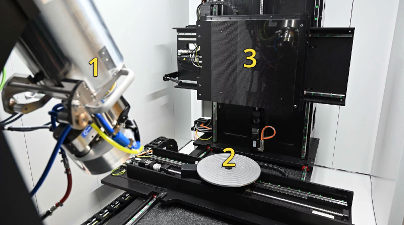
What is 3D Laser Scanning?

What is 3D Scanning?

In the dynamic landscape of modern manufacturing, precision is paramount. Enter 3D scanning – a transformative technology reshaping the way industries approach quality control, reverse engineering, and dimensional inspection. At its core, industrial 3D scanning utilizes advanced data capture techniques to produce detailed, three-dimensional representations of physical objects with unprecedented accuracy. But what exactly is industrial 3D scanning for, and how is it revolutionizing the manufacturing landscape?

Hexagon AS1 Laser Scanner
Hexagon Portable AS1 Laser Scanner
CAD COMPARISONS

In manufacturing, ensuring product quality is non-negotiable. Industrial 3D scanning plays a pivotal role in this endeavor by providing manufacturers with the means to meticulously inspect entire components and assemblies for defects, deviations, and inconsistencies. From intricate aerospace parts to automotive components, 3D scanning offers a comprehensive solution for identifying imperfections early in the production process, minimizing waste, and optimizing product performance.

Scan to CAD Deviation Map of Engine Nozzle
DIMENSIONAL INSPECTION

Precision is the hallmark of quality, and dimensional accuracy is a critical aspect of manufacturing excellence. Industrial 3D scanning provides manufacturers with a reliable method for verifying the dimensional integrity of components and assemblies, ensuring they meet tight tolerances and specifications. By comparing scanned data to CAD models or reference standards, manufacturers can confidently validate the accuracy of their products, safeguarding against costly errors and rework.

SPC
SPC Charts & Dimesional Results in PolyWorks Software
REVERSE ENGINEERING

The ability to replicate and improve upon existing designs is a cornerstone of innovation. Industrial 3D scanning facilitates this process by capturing the exact geometry of physical objects, allowing engineers to create digital models that can be modified, optimized, or reproduced as needed. Whether it’s redesigning legacy components or enhancing product functionality, 3D scanning enables manufacturers to unleash their creativity and drive continuous improvement.

Scan to Geometric CAD Models using Geomagic Design X Software

In conclusion, industrial 3D scanning is a versatile and indispensable tool that empowers manufacturers to achieve new levels of precision, efficiency, and innovation. Whether it’s enhancing product quality, accelerating design iterations, or ensuring dimensional accuracy, 3D scanning is reshaping the manufacturing landscape and driving advancements across industries. As technology continues to evolve, the potential of industrial 3D scanning to unlock new possibilities and propel us towards a future of manufacturing excellence is boundless.

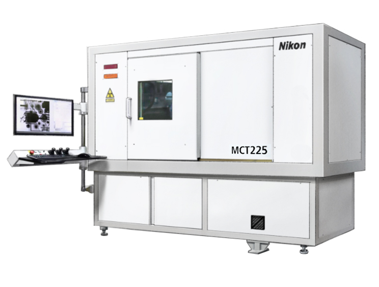
What is Industrial CT Scanning?

THE BASICS OF INDUSTRIAL CT SCANNING

Industrial CT scanning systems have revolutionized the way we inspect and analyze objects in a wide range of industries, from aerospace to automotive and beyond. At the heart of these systems lies a remarkable technology that enables us to peer inside solid objects with unprecedented clarity and detail. So, how exactly do industrial CT scanning systems work?

MCT2
Industrial CT Scanning Cabinet

THE HARDWARE

At its core, industrial CT scanning operates on principles similar to medical CT scans but tailored for industrial applications. The process begins with the object of interest being placed on a rotating platform within the CT scanner. Next, a powerful X-ray source emits radiation, which penetrates the object as it rotates. The radiation that passes through the object is captured by a detector on the other side. This interaction results in a series of 2D X-ray images, or “slices,” which collectively provide a comprehensive view of the object’s internal structure.

1. X-Ray Source,    2. Part Manipulator,    3. X-Ray Detector

Industrial CT Scanning Components

THE SOFTWARE

But here’s where the magic truly happens: sophisticated software algorithms reconstruct these individual slices into a 3D model, akin to assembling a virtual puzzle. This 3D model reveals intricate details such as internal features, defects, and material density variations that are crucial for quality control, defect analysis, and product optimization.

1. Thousands of X-Ray Images,    2. Building 3D File from 2D Images,    3. Analyzing 3D File using Volume Graphics Software

Reconstructing a Geode Scan

THE PURPOSE

What sets industrial CT scanning apart is its ability to examine objects with complex geometries, varying materials, and internal structures that are otherwise inaccessible to traditional inspection methods. From intricate aerospace components to dense automotive parts, industrial CT scanning offers a non-destructive and highly accurate means of evaluation, saving both time and resources while ensuring product integrity.

3D Evaluation of Bellows Weld

Moreover, as technology advances, so do the capabilities of industrial CT scanning systems. With advancements in X-ray sources, detectors, and computational algorithms, these systems can now achieve higher resolution, faster scan times, and enhanced image quality, further expanding their utility across industries.

Investing Leaks in Tubes

In conclusion, industrial CT scanning systems represent a groundbreaking advancement in inspection and analysis technologies. By harnessing the power of X-rays and sophisticated software, these systems enable us to see beyond the surface and delve into the inner workings of objects, paving the way for safer, more efficient, and higher-quality products across diverse industries.

What is Industrial X-Ray Imaging?

Industrial X-ray services are the unsung heroes of modern manufacturing, providing invaluable insights into the inner workings of complex components and materials. From aerospace to automotive industries, these services utilize X-ray technology to peer beneath the surface, uncovering defects, assessing structural integrity, and ensuring product quality with unparalleled precision.

THE HARDWARE

At the heart of industrial X-ray services lies advanced imaging technology that enables the creation of detailed, high-resolution images of objects’ internal structures. This non-destructive testing method allows manufacturers to scrutinize components without compromising their integrity, saving time and resources while maintaining product reliability.

1. X-Ray Source,    2. Part Manipulator,    3. X-Ray Detector

Industrial CT Scanning Diagram

Whether it’s inspecting welds for cracks, detecting voids in castings, or analyzing composite materials for delamination, industrial X-ray services offer a versatile solution for a wide range of applications. With customizable inspection protocols and state-of-the-art equipment, these services can adapt to the unique needs of various industries, providing tailored solutions for quality assurance and defect analysis.

dr 1

Moreover, industrial X-ray services play a crucial role in ensuring regulatory compliance, particularly in safety-critical industries where the integrity of components is paramount. By leveraging X-ray technology, manufacturers can uphold the highest standards of quality and safety, mitigating risks and enhancing customer trust.

Power Drill XRay 1

In conclusion, industrial X-ray services represent a cornerstone of modern manufacturing, offering a glimpse into the hidden world of materials and components. With their ability to uncover defects, assess structural integrity, and ensure compliance, these services empower manufacturers to deliver products of uncompromising quality, driving innovation and excellence across industries.

X-RAY PCB 2

Reasons for Using a CT Scanning Laboratory

Are you searching "Industrial CT Scanning Near Me?"

Navigating Industrial CT Scanning: Local Challenges, Nationwide Solutions

In the realm of industrial CT scanning, there’s a prevailing wisdom: sometimes, the best solution lies beyond your doorstep. While the idea of sending your projects across the country may seem counterintuitive at first glance, a closer examination reveals the compelling reasons why clients should consider this inspection method. Let’s explore why bypassing local inspection options in favor of industrial CT scanning solutions can lead to superior outcomes.

MCT2
Access to Cutting-Edge Technology

When it comes to CT scanning, not all facilities are created equal. While your local options may offer 3D scanning capabilities, they might lack the cutting-edge technology necessary for complex projects. By widening your scope to include facilities across the country, you gain access to state-of-the-art equipment and advanced scanning techniques that can uncover insights and nuances impossible to detect otherwise. From intricate aerospace components to delicate medical devices, investing in superior technology ensures unparalleled accuracy and reliability.

Valve Cover
Specialized Expertise

CT scanning is as much an art as it is a science. It requires a deep understanding of materials, meticulous attention to detail, and years of hands-on experience. While a local facility may boast competent technicians, truly exceptional results often stem from specialized expertise. A multi-method inspection lab aggregates the best talent from across the country, ensuring that your projects are handled by seasoned professionals with a track record of excellence. Whether it’s deciphering complex scans or troubleshooting unexpected challenges, tapping into this wealth of expertise can elevate the quality of your outcomes.

PCB Solder Pad Porosity CT Scan
Rigorous Quality Standards

In industries where precision is paramount, quality control is non-negotiable. CT scanning facilities adhere to rigorous quality standards and certifications, providing clients with the assurance that their projects are in capable hands. Industrial Inspection maintains industry-specific certifications like NAS410 & ASNT, ensuring quality at every stage of the inspection process. By entrusting your projects to reputable facilities with a proven commitment to excellence, you mitigate the risk of errors, delays, and costly rework.

Medium_Bookmark 3
Unbiased Third-Party Validation

In today’s global marketplace, transparency and accountability are essential. Sending your projects to a third-party CT scanning facility across the country offers an added layer of credibility and objectivity. Unlike in-house scanning solutions, which may be susceptible to bias or conflicts of interest, external facilities provide unbiased assessments based solely on empirical data. This impartial validation not only enhances the credibility of your products but also instills confidence among stakeholders, from clients to regulatory agencies.

3
Future-Proofing Your Investments

Using a national CT scanning lab isn’t just about meeting current needs—it’s about future-proofing your investments. By aligning yourself with cutting-edge technology and top-tier expertise, you position your business for long-term success and innovation. As industries evolve and technologies advance, having access to best-in-class scanning capabilities ensures that you remain at the forefront of your field. Whether it’s staying ahead of regulatory requirements or pioneering breakthroughs in product development, the benefits of forward-thinking investment extend far beyond immediate gains.

Stator
Conclusion

In the dynamic landscape of industrial CT scanning, proximity should never be a barrier to excellence. By embracing the advantages of nationwide solutions, clients can unlock a world of possibilities for their projects. From access to cutting-edge technology and specialized expertise to rigorous quality standards and unbiased validation, the benefits of sending projects across the country are clear. In an era defined by innovation and competition, choosing the right CT scanning partner isn’t just a decision—it’s a strategic imperative.

Geometric Magnification Explained – 40um vs 8um CT Scan of Sensor

WHY RESOLUTION MATTERS

For x-ray & CT imaging there is a dynamic called Geometric Magnification. GeoMag (Mg) is the calculation of the distance between the x-ray source to test object and detector (Source to Object Distance, SOd) & (Source to Detector Distance, SDd).

If the detector remains stationary, the closer the object moves to the x-ray source the higher the resolution becomes. However, the further the object moves from the detector, the smaller the field of view. Put simply, the higher the resolution, the smaller the area of interest to be imaged.

A proper understanding of the project requirements determines the appropriate resolution and field of view. If a client needs to check for hairline fractures or micro-porosity, maximum resolution is necessary. If these defects are smaller than the resolution of the data they may not be resolved.

The below sensor is being scanned to evaluate potential leak paths in the soldered tip. The advantage of the 40um scan is that the entire part is characterized. However, the fine details of the area of interest are best resolved in an area of interest scan at 5x that resolution. At this resolution we can see micro-porosity not seen in the larger GeoMag scan.

40um Full Part Scan

8um Area of Interest Scan