MEASURING TEST TUBES & VIALS FOR WALL THICKNESS AND VOLUME
CT scanning plays a pivotal role in assessing the wall thickness and volume of glass components, offering critical insights for manufacturing processes and product quality. Glass, known for its brittleness and susceptibility to defects, requires meticulous inspection to ensure structural integrity and performance. CT scanning provides a non-destructive means of examining these components, offering precise measurements of wall thickness and volume with unparalleled accuracy. By detecting variations in thickness and identifying potential flaws, CT scanning enables manufacturers to optimize production processes, enhance product reliability, and uphold stringent safety standards. The comprehensive evaluation provided by CT scanning ensures that glass components meet the highest quality requirements, ultimately contributing to safer and more durable end products.
CT SCANNING TO MEASURE WALL THICKNESS
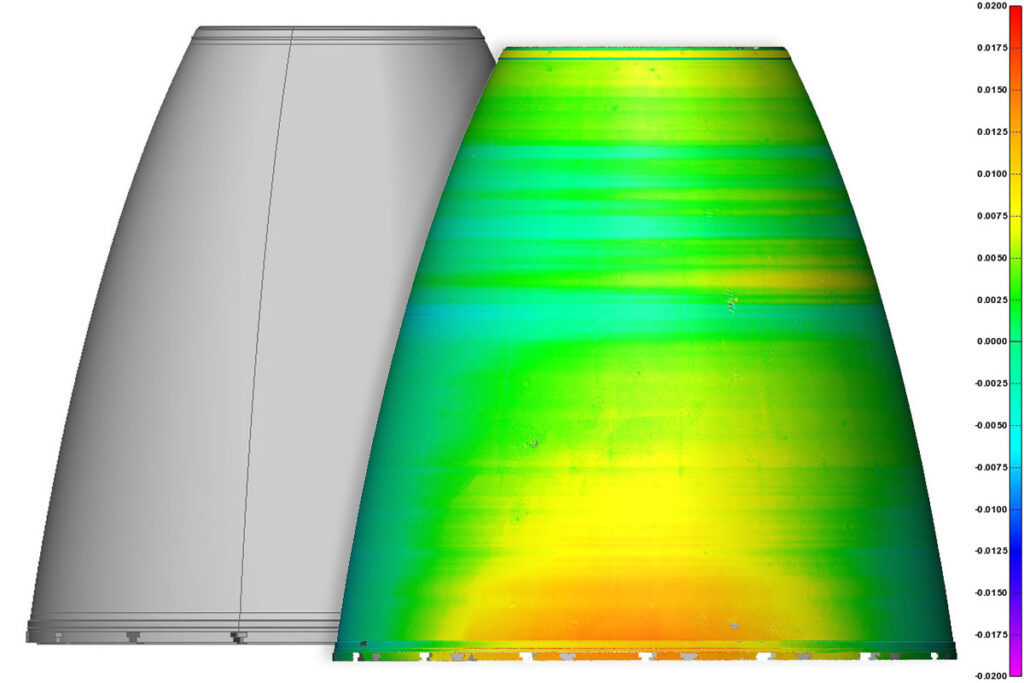
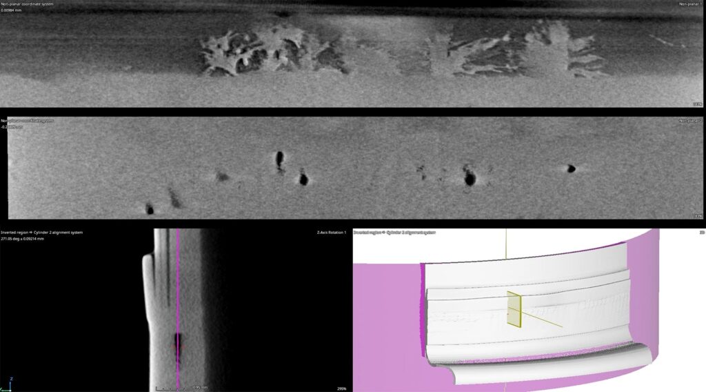
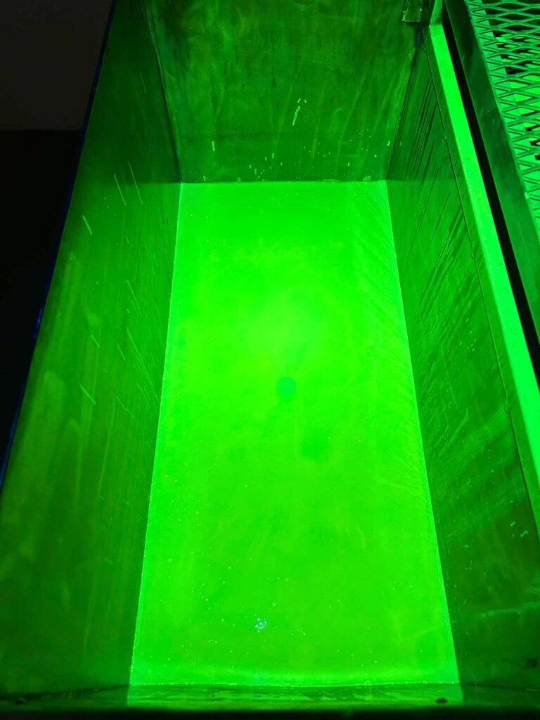
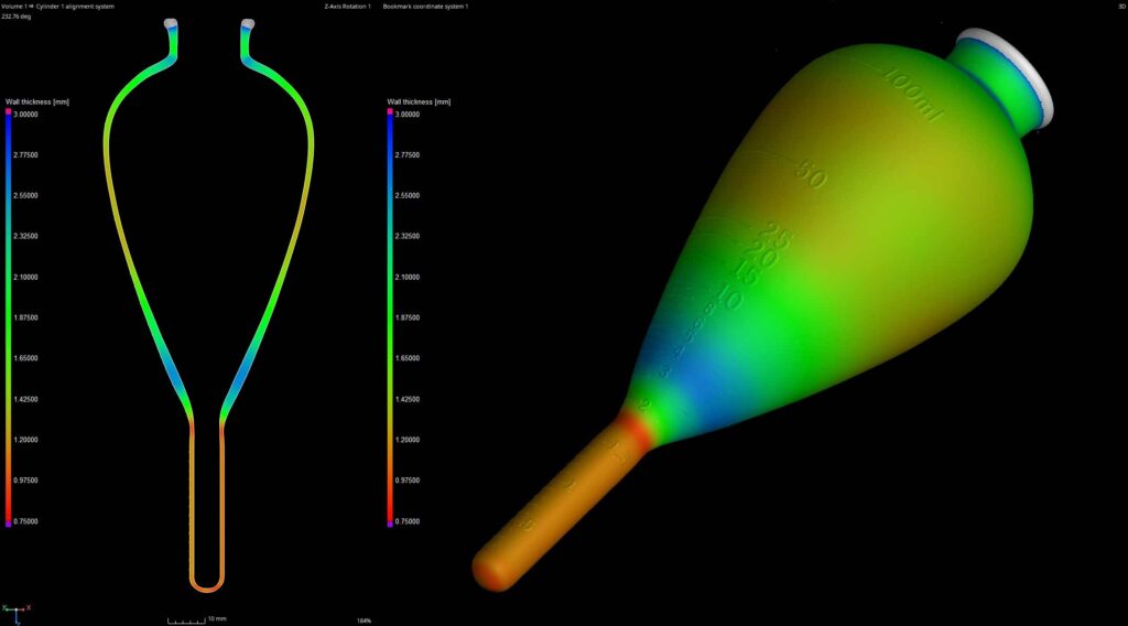
CT scanning is used for evaluating wall thickness in a wide range of materials and structures. By utilizing X-ray technology to penetrate objects, CT scanning generates detailed 3D images that allow for precise measurements of wall thickness. This non-destructive technique is invaluable for industries such as manufacturing, aerospace, and automotive, where ensuring structural integrity is paramount. This image demonstrates a total mapping of the thickness of the tube with variable results from .75mm to 2.55mm.
VOLUME OF GRADUATION MARKS
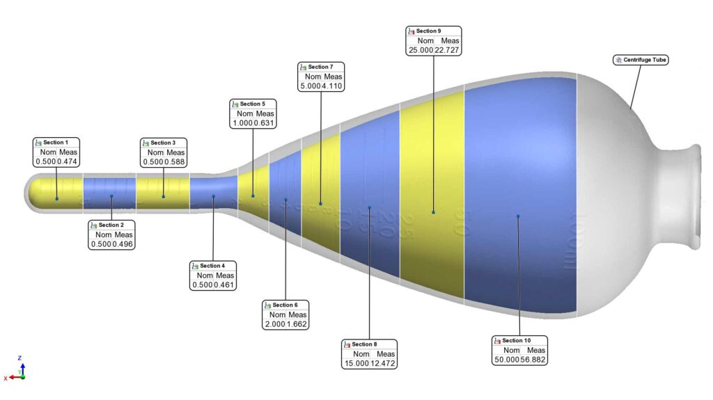
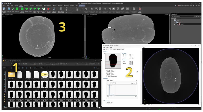
CT scanning offers a precise and non-destructive method for measuring volume in objects with complex geometries. We were able to segment, virtually cap, and extract volumetric measurements of the tube at various graduation marks.
The nominal “as-marked” volume states 100ml and the measured volume equals 100.533ml – a deviation of just 0.5% of the volume. However, sub-sections like section 5 have a deviation of 27%.