Scanning technologies are used to reverse engineer tooling die steels. Over time steel wears, breaks, or is modified to produce a better part. Design files become lost or do not match the modifications.
Using our high resolution laser pCMM we can reproduce worn die steels into toolable .step CAD models.
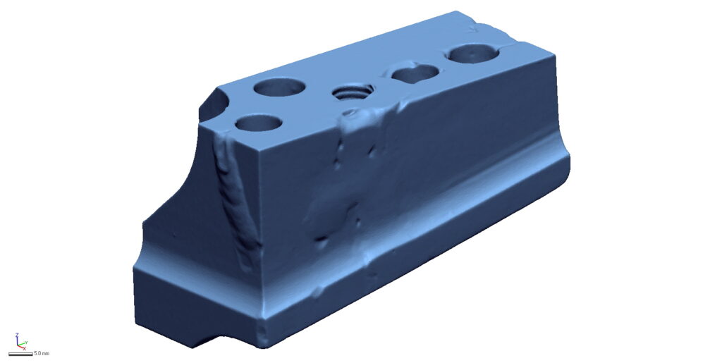
STEP 1ACQUIRE SCAN DATA
Lorem ipsum dolor sit amet, consectetur adipiscing elit. Ut elit tellus, luctus nec ullamcorper mattis, pulvinar dapibus leo.
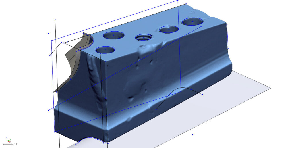
STEP 2SKETCH THE GEOMETRY
Geomagic Design X offers a large variety of modeling tools like 2D sketching, extrusions, lofting, patterning, and symmetry.
Assets are created and merged into a solid model.
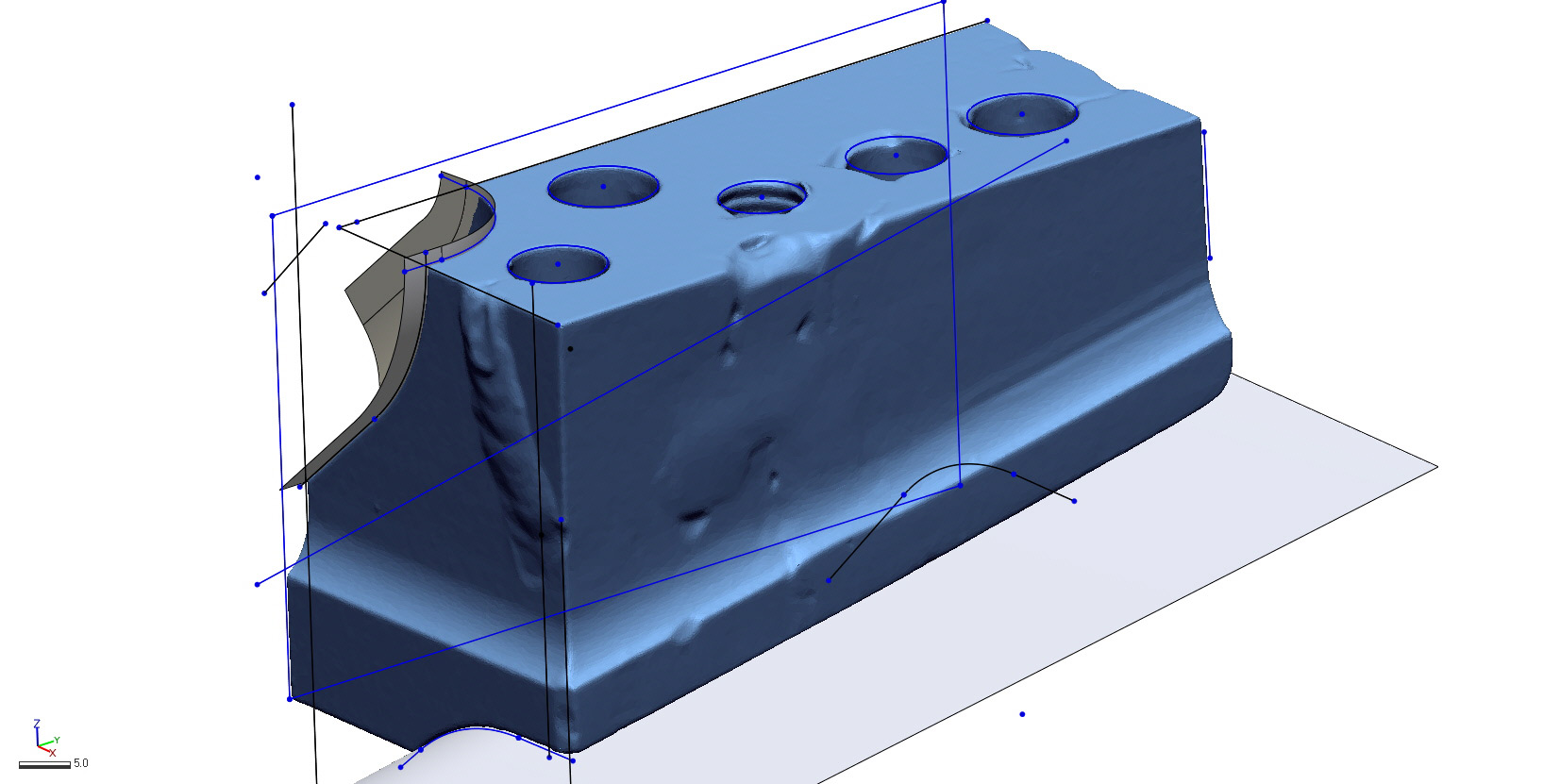
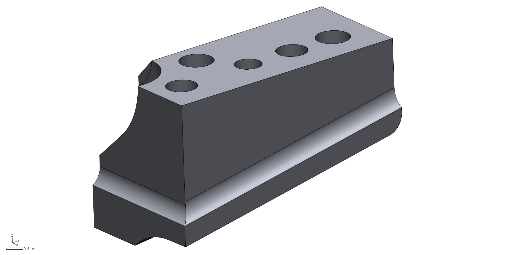
STEP 3TUNE THE MODEL
After a model is created it is tuned to achieve the minimal amount of deviation. Sometimes surfaces need to be moved or hole sizes adjusted.
STEP 4REPORT THE DEVIATION
The deliverables for every reverse engineering project include a final .step model as well as a deviation report. This profile heat map shows the areas where the produced model differentiates from the original scan file.
Sometimes deviation is inevitable where a cracked component was stitched back together, while other times a free-form surface cannot be perfectly geometrically replicated.
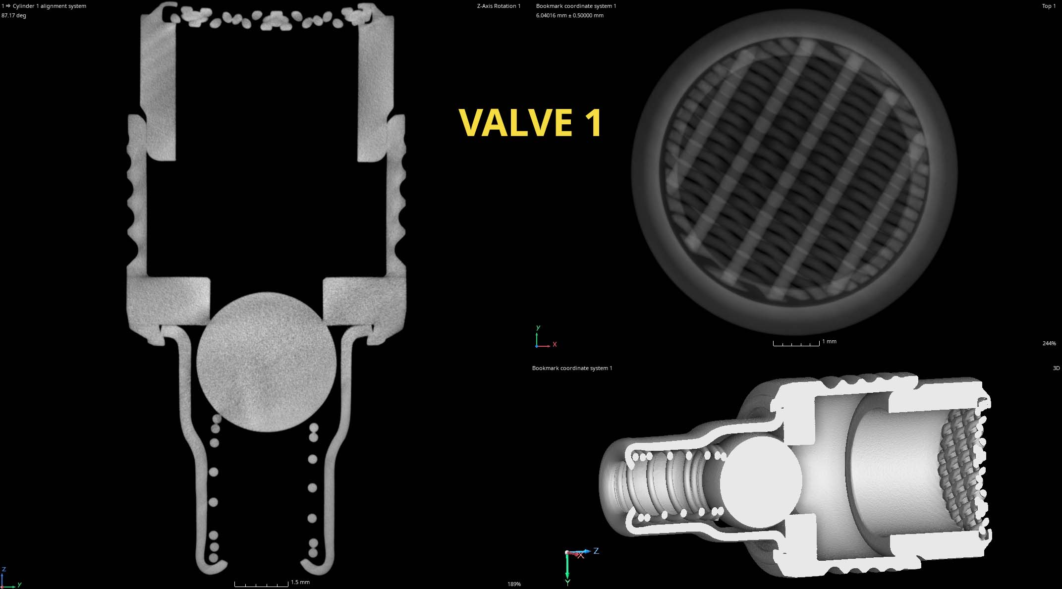
Miniature fluid control components are used in every industry – from scientific instruments like respirators, to defense systems like missile seekers, and automotive EV battery heaters and coolers.
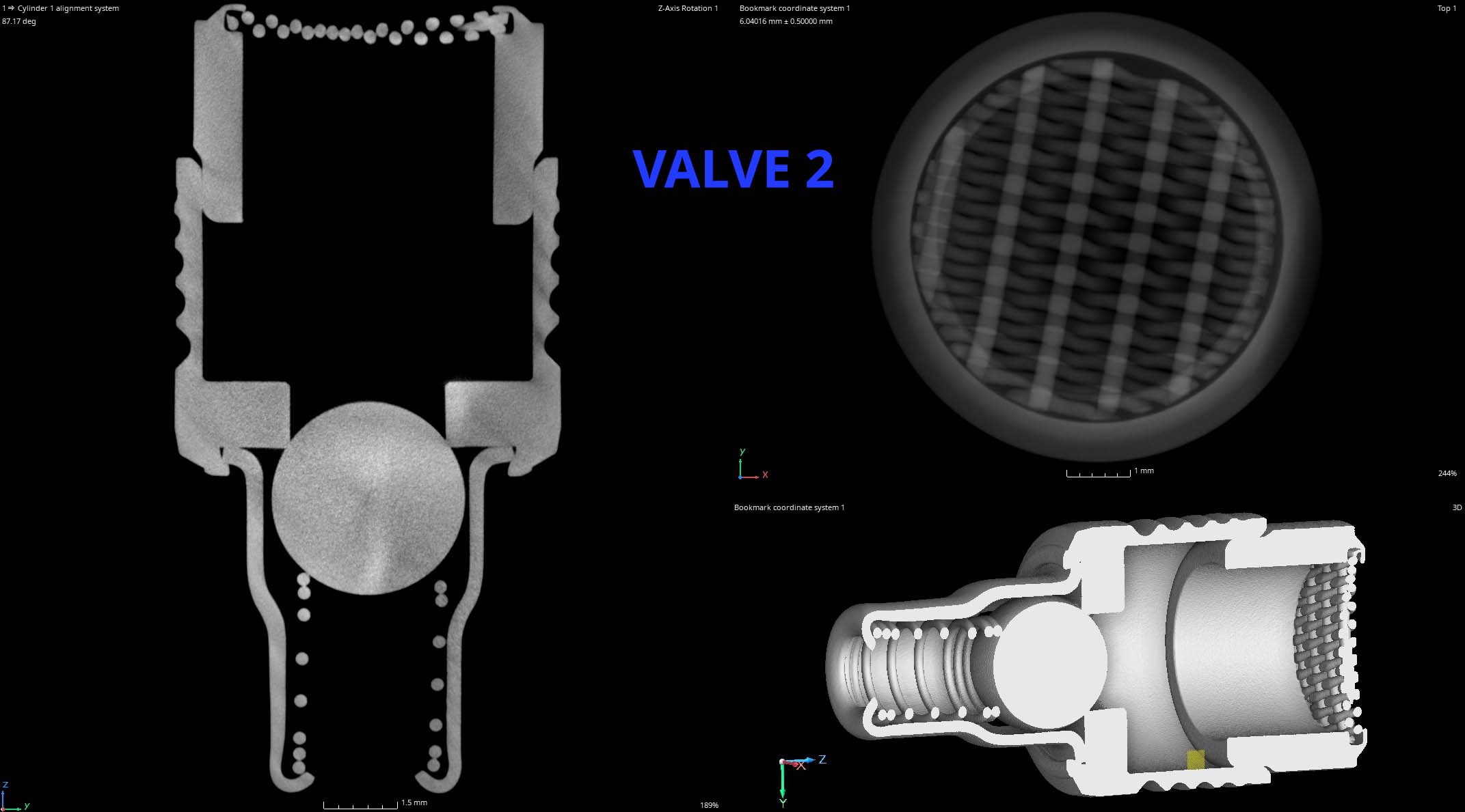
This case study characterizes two stainless steel, mesh screened micro check valves smaller than a dime. We demonstrate CT slice comparisons of the components as well as our measurement capabilities using PolyWorks.
We are able to measure wall thickness, check for component orientation like the spring, ensure the ball seats properly, and image the screen weld.
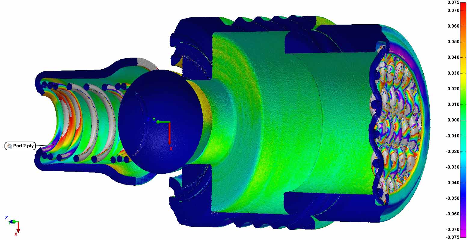
If one part is functioning differently than another we can create a color coded heat map showing the differences.
Part to Part Profile Comparison
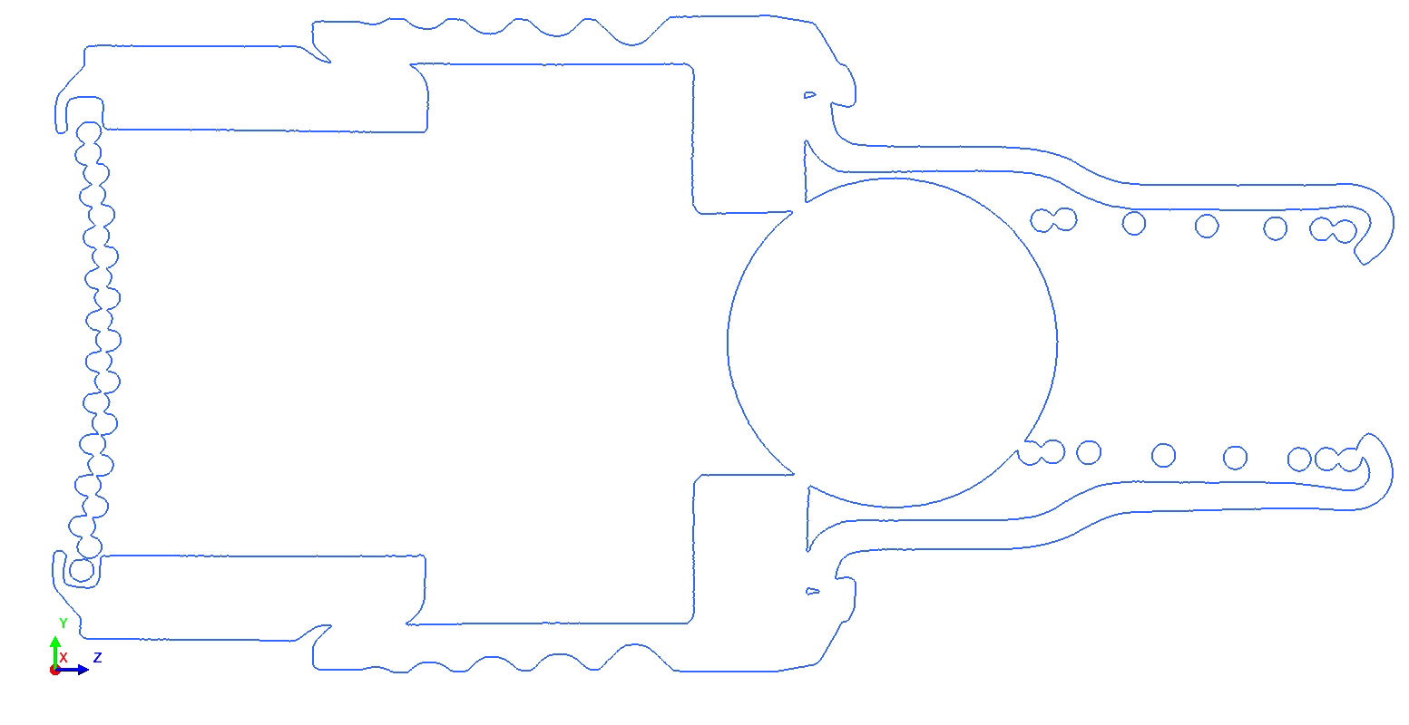
Profile of a Line for Shape & Orientation
.125um Screen Weld Characterization
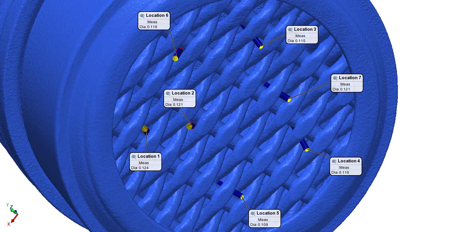
Tangible Measurement of Screen Pore Tolerance
We defined best fit cylinders into the screen gaps to understand the actual diametral width of the screen. We found that the screen, indeed, does not allow any contaminant above 125um diameter through.
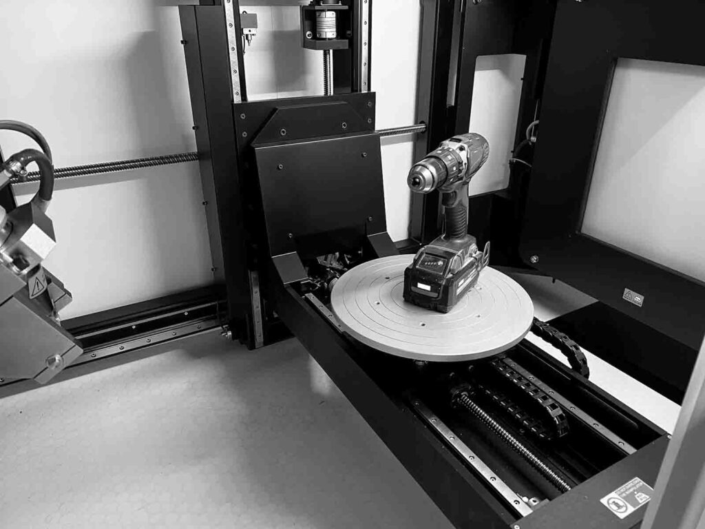
Industrial X-Ray & CT inspection services allow our clients to inspect the internal geometry of their products. This case study explores a power drill. We’ve worked on a variety of home goods like coffee grinders, chainsaw starters, shaver bladers, and mouthwash caps.
High resolution x-ray and CT also allows technicians to measure internal, inaccessible geometry, evaluate fine details like wire bonds and porosity in solder joints, and characterize leak paths in consumables.
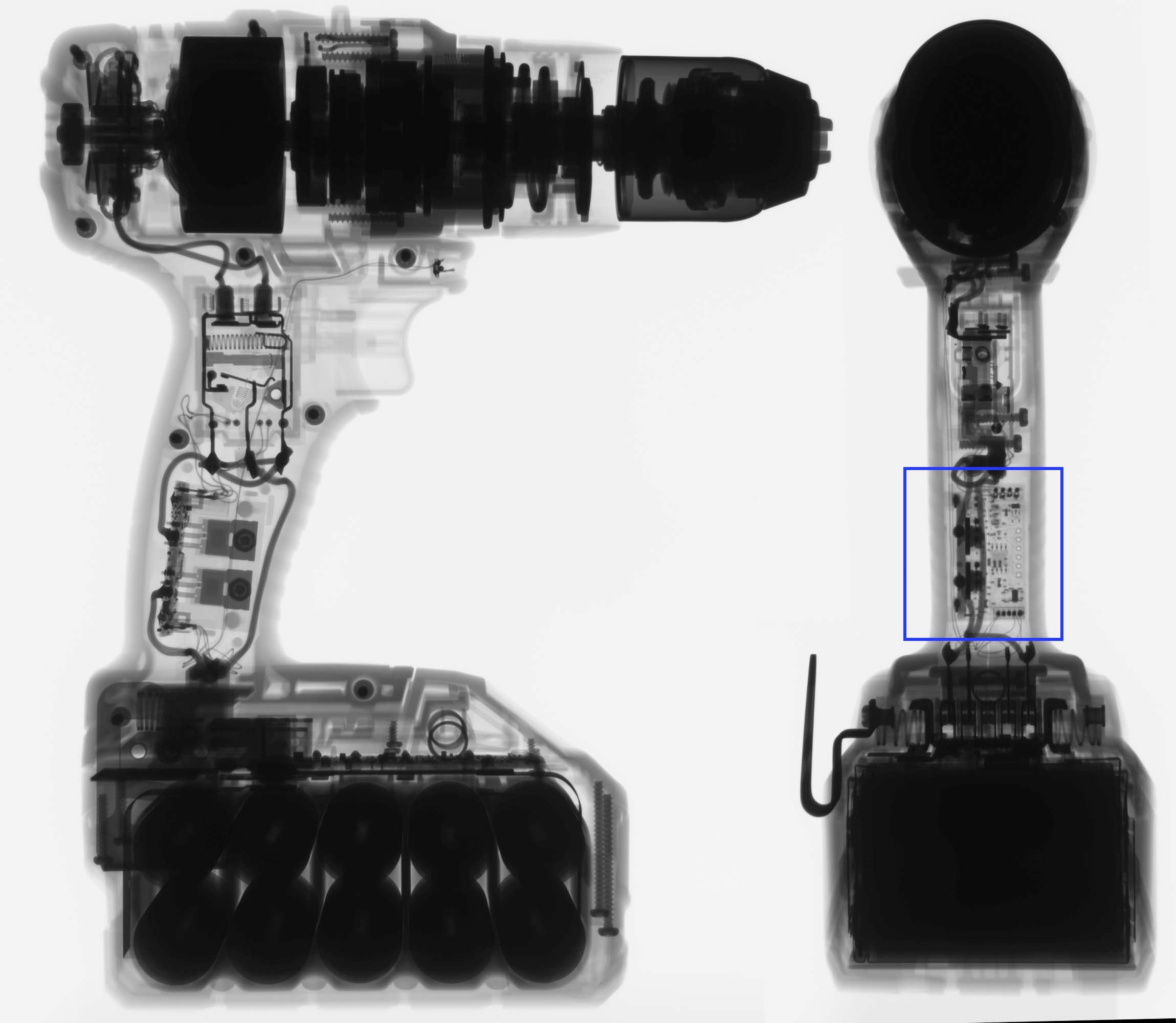
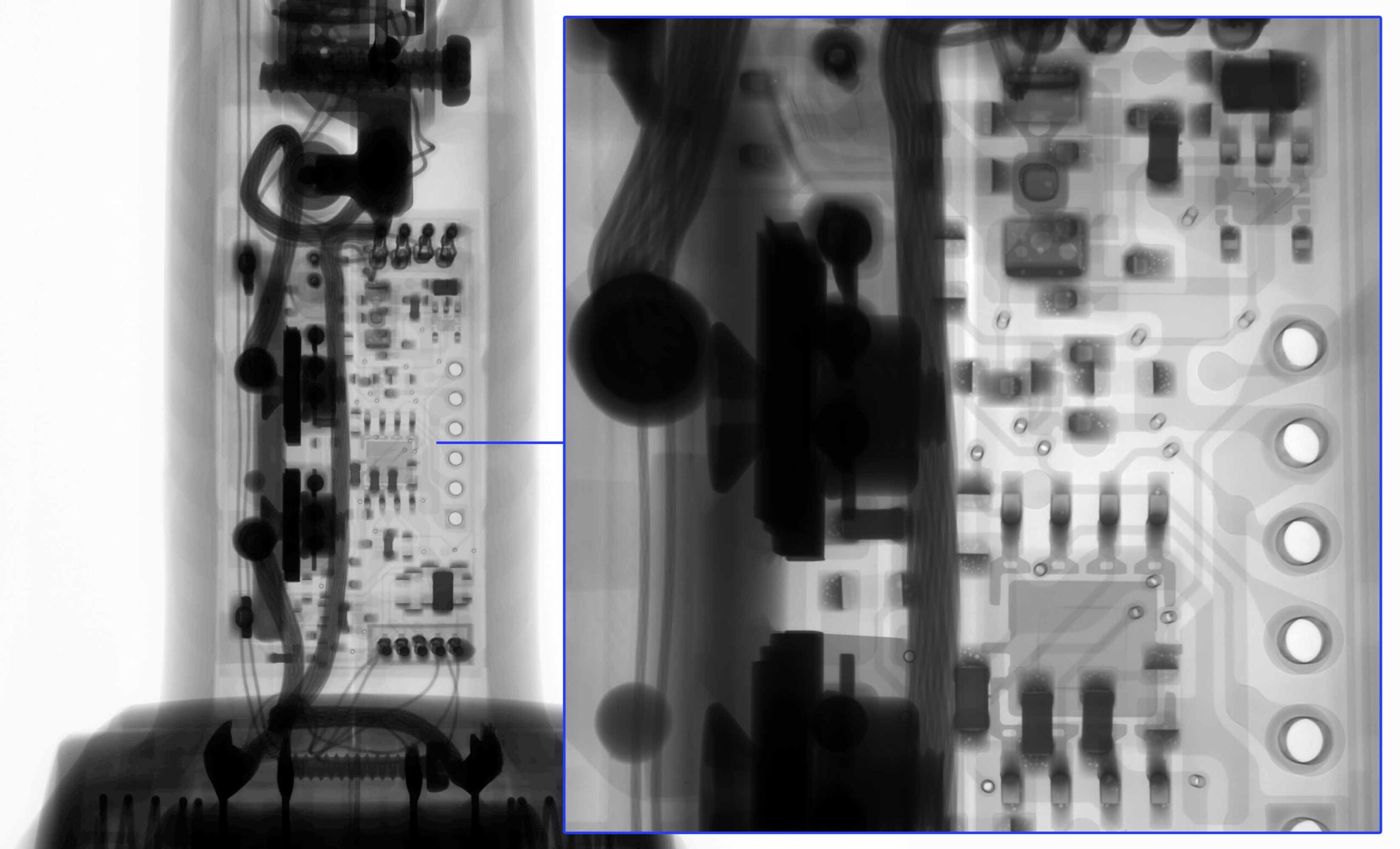
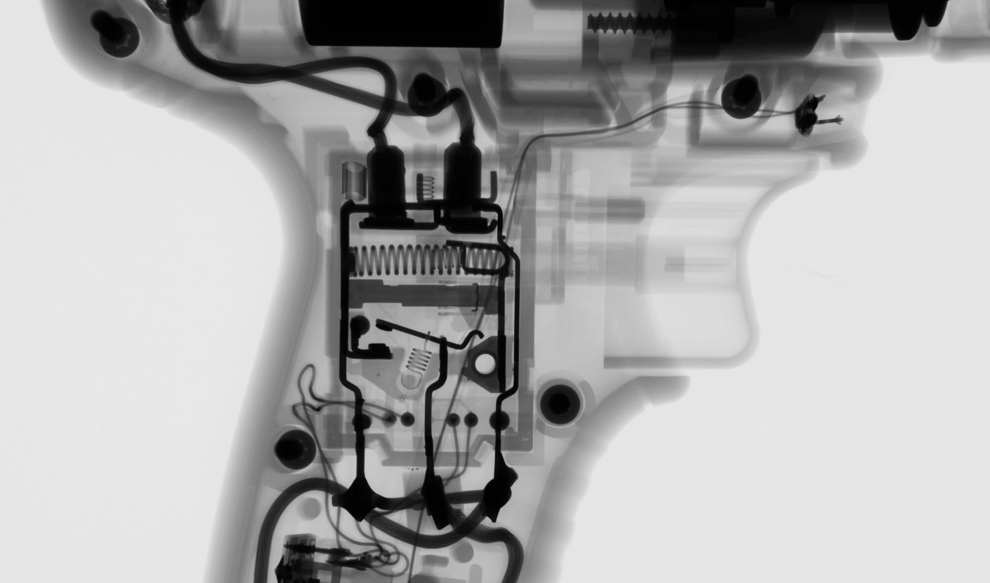
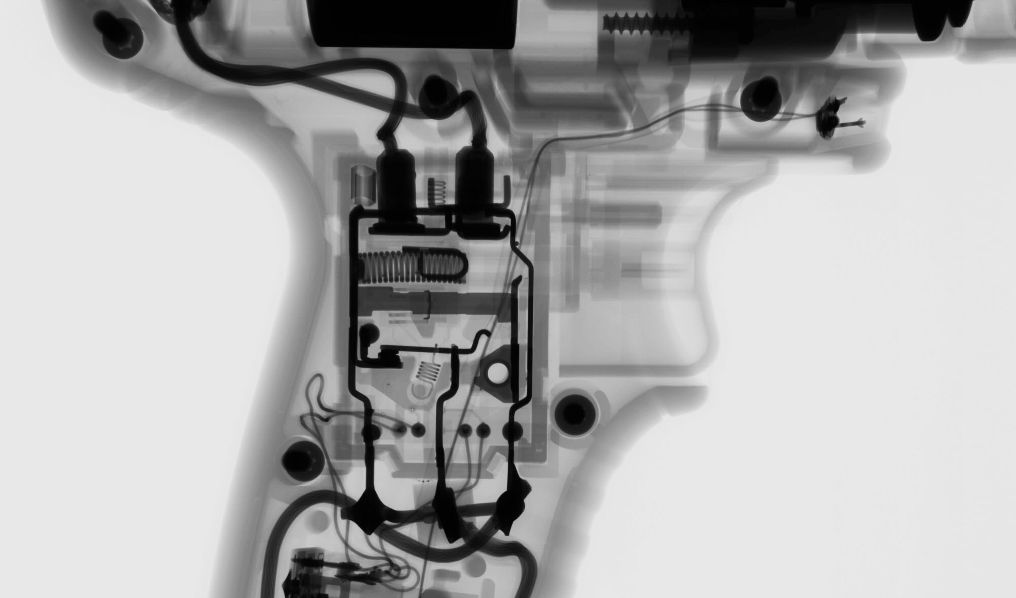
General Digital X-Ray Images of Power Drill
Our digital x-ray systems have variable resolution ranging from 3um to 125um. This allows us to image very small and very large objects. This drill could be imaged at low resolution for general component placement (springs are in position) or at high resolution to detect and calculate porosity in the PCB joints.
Pre-to-Post actuation is useful for understanding the dynamics of a complex assembly. For example, happens when something is powered up? How much clearance is there when a lever is pressed? Fill the blank with your own scenario and consider letting Industrial Inspection quantify it for you.
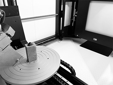
INDUSTRIAL CT SCAN OF POWER DRILL
2D Digital radiography is great for a general understanding of components. However, 3D CT scanning allows inspectors to produce tangible, complex measurements of devices. For example, we could measure the concentricity the chuck components, the profile of the handle, or the depth wires are placed into a connector.
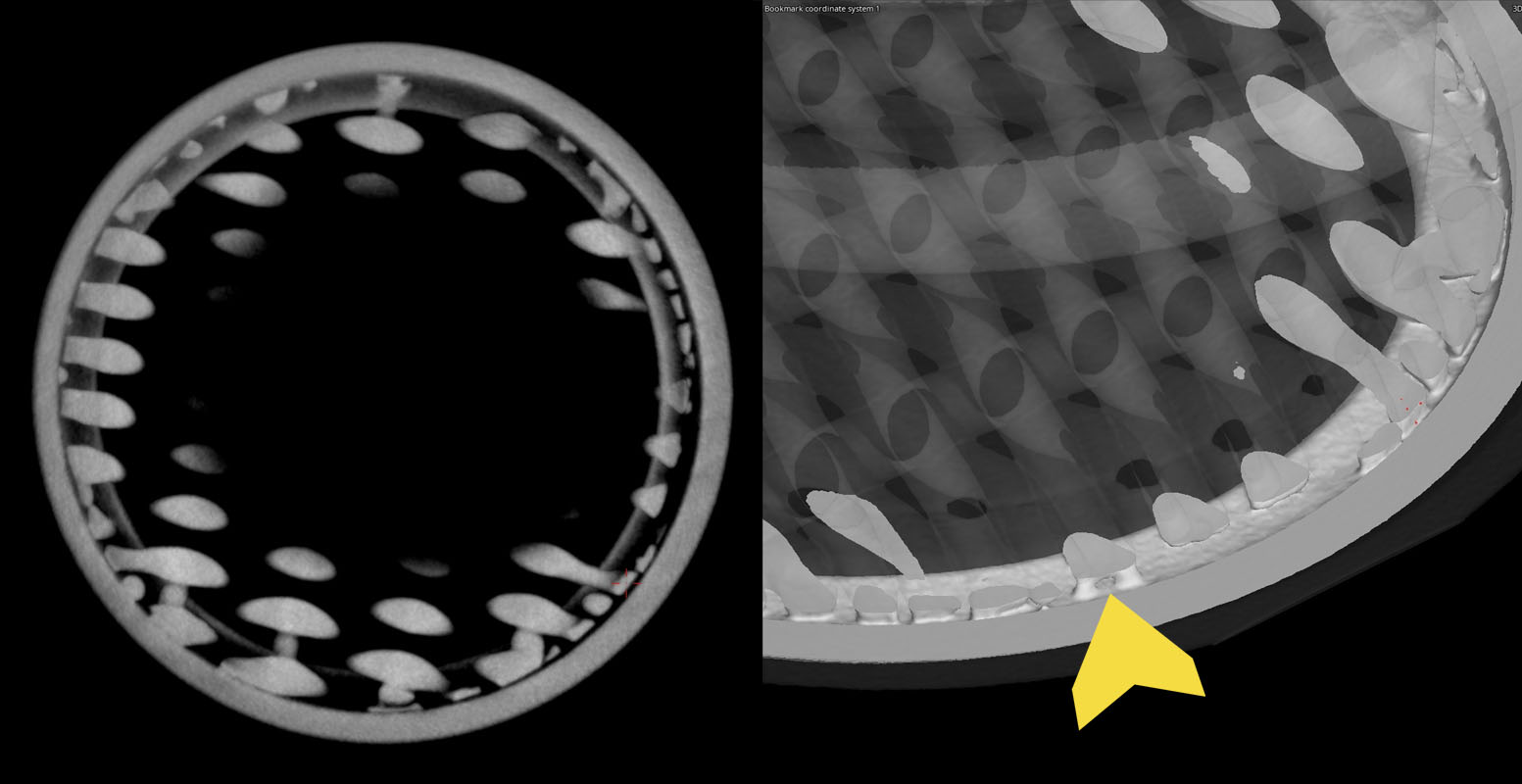
CHARACTERIZING AM COMPONENTS USING INDUSTRIAL CT SCANNING
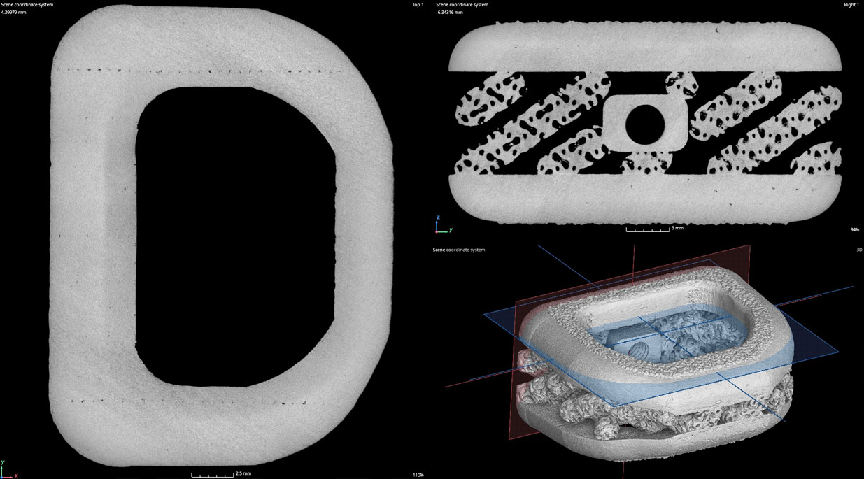
Industrial CT Scanning is used to characterize 3D Printed / Additively Manufactured components. A strength of these components is the ability to manufacture complex geometries that more traditional manufacturing methods are incapable of producing. However, because of the part complexity more traditional inspection methods like tactile probes and vision system are inadequate. CT scanning can be used to dimensionally inspect and non-destructively evaluate these components for rejectable flaws (porosity, trapped powder, wall thickness, & profile.)
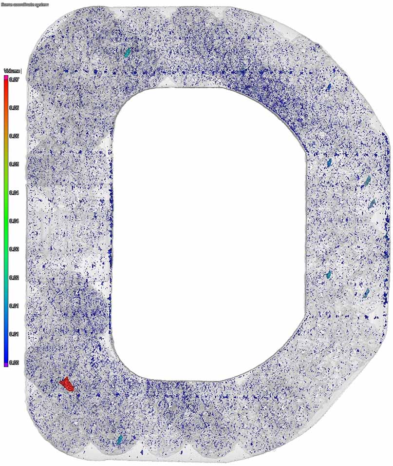
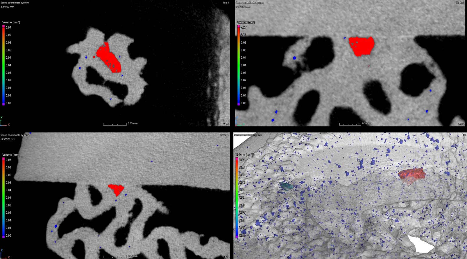
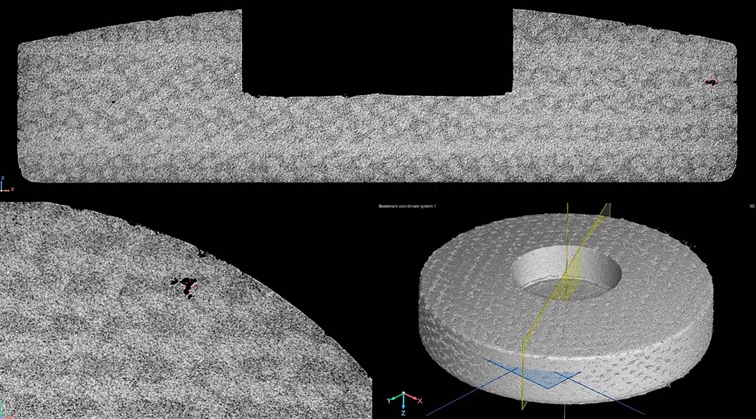
POROSITY ANALYSIS
Porosity can be volumetrically extracted and analyzed for porosity percentage, distribution, 3D rendered for visual comparisons between process changes, or exported to .stl to be used in other software packages.
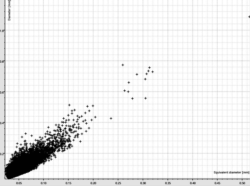
Distribution of pore size and equivalent diameter
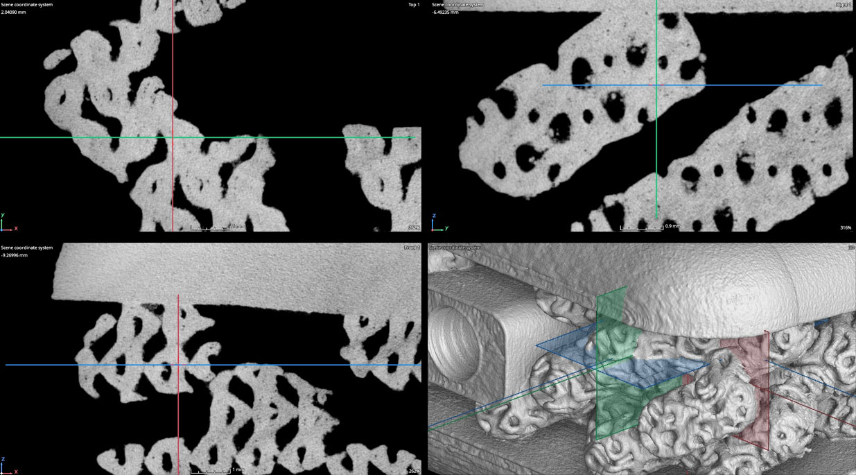
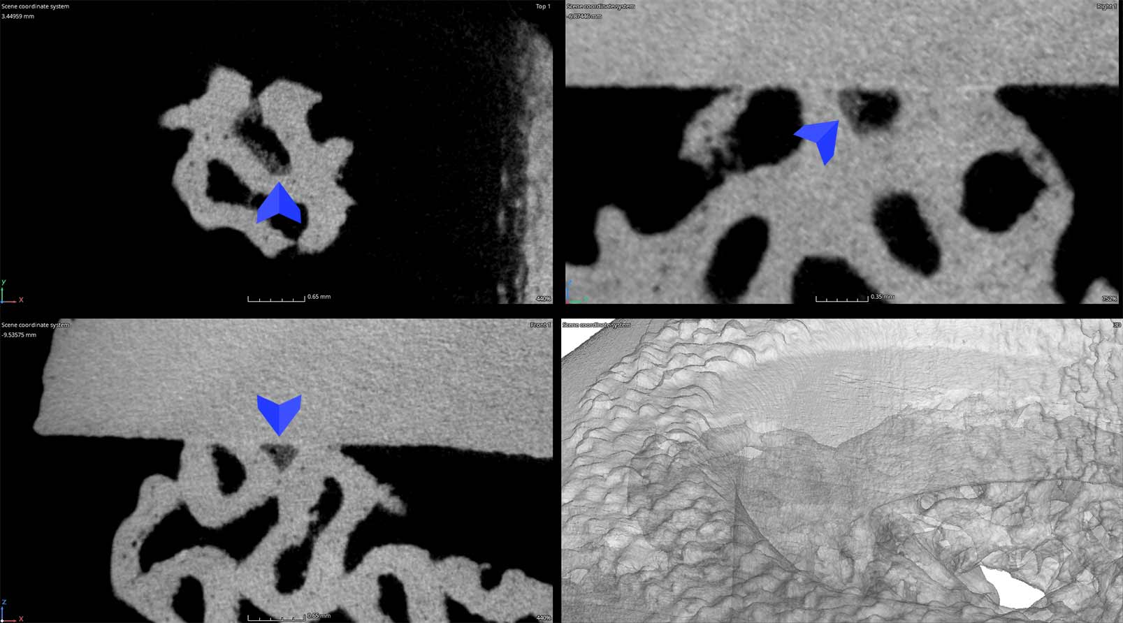
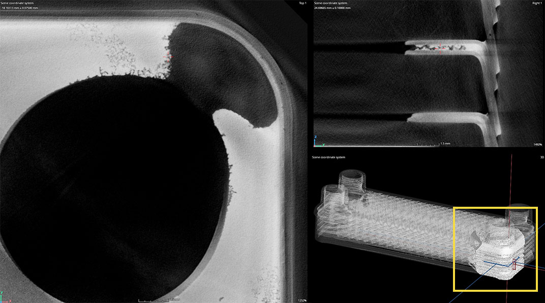
TRAPPED POWDER INSPECTION
Industrial CT scanning is used to analyze additively manufactured products for trapped powder. If trapped powder is not completely removed from products, its release during product service lifetime could cause serious problems. For medical implants with materials that are supposedly biocompatible, metallic powder can cause inflammation and prevent normal blood vessel formation. [Source] The image below shows an area of interest that should be open to the surface but closed during manufacturing. The trapped powder is seen as a slightly lighter shade of gray compared to the neighboring geometry.
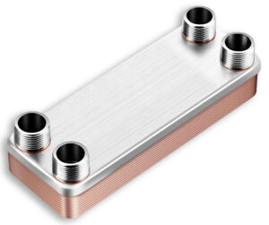
Characterizing Leak Paths in Brazed Copper Heat Exchangers
Heat exchangers are devices that transfer heat from one medium to another using a network of channeled circuits. We’ve CT scanned most types of heat exchangers including shell & tube to image tube array welds and plate type exchangers to evaluate brazes and leak paths.
This case study uses a common copper plate type heat exchanger which contains a network of channels that fluid passes through.
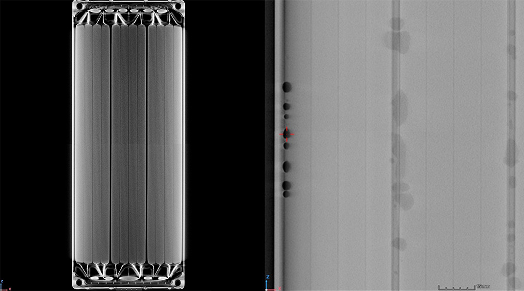
As seen below in the general part scan there are indications of porosity and gaps in the corner and edges which may be causing the part to leak.
Once an area of interest has been determined we can increase resolution to provide better detail of the failure. This partial scan at just the corner reveals that the entire corner is missing brazing material and there are also leak paths in proximity. The customer uses this information to adjust their manufacturing process.
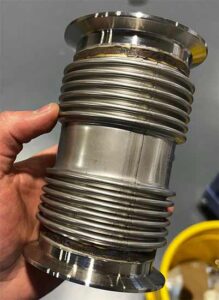
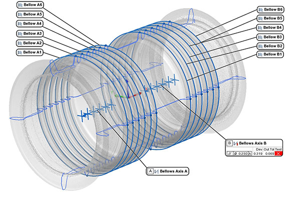
Bellows are a type of expansion joint used in piping applications for a variety of industries like oil & gas, aerospace and defense. Bellows allow complex systems to move according to the forces applied to them (system vibrations, pressure changes, & rapid temperature shifts).
Because bellows are used to sustain a system through the above factors their structural integrity is paramount. This case study demonstrates the method of CT scanning to image and qualify bellows welds and ply separation.
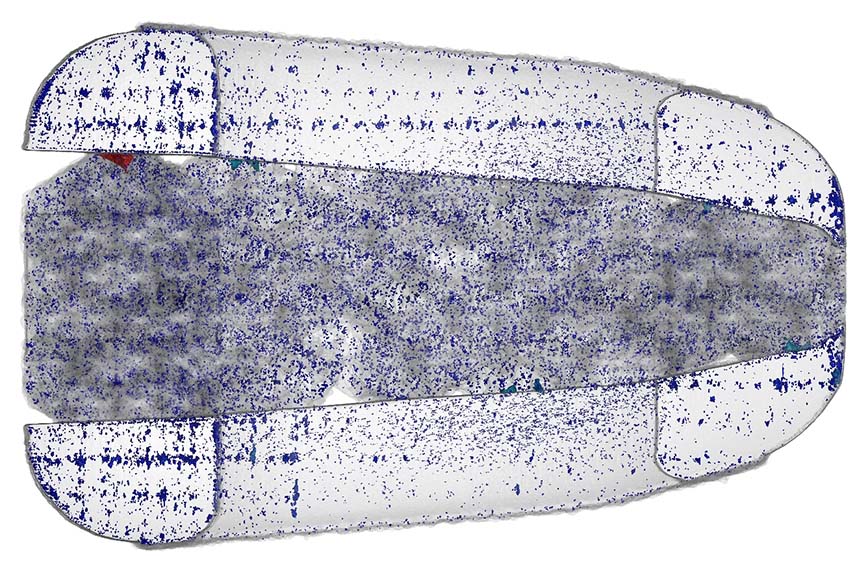
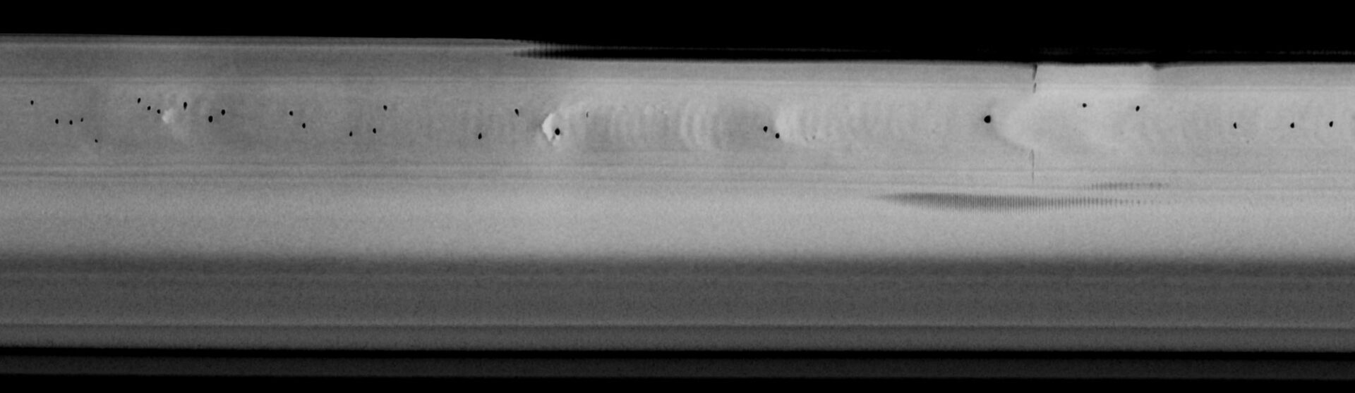
UNROLL METHOD
The “Unroll” technique offers a planar viewing method for cylindrical features or parts. Below is an unrolled, higher zoom view of the weld, porosity, and sleeve seam.
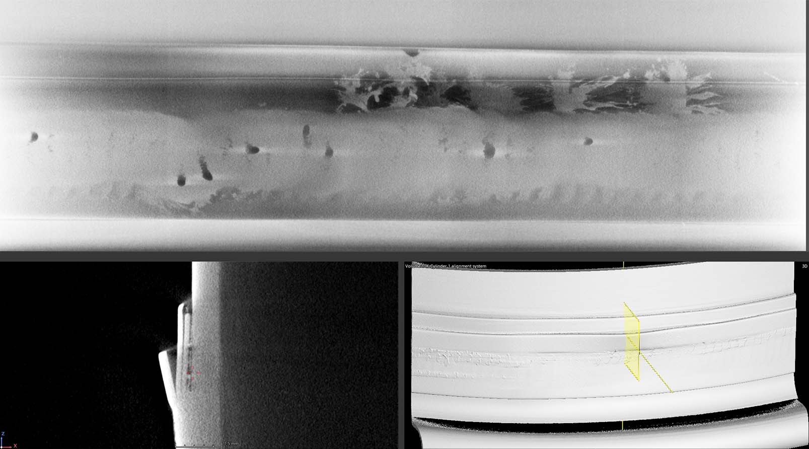
FOCUS SCAN (20um RESOLUTION)
During process development engineers often request the highest possible resolution of an area of interest. This characterization helps inform the engineer for process changes and product viability.
DIMENSIONAL INSPECTION
Industrial CT data, and surface data acquired using laser scanning (click here to learn more), is exported to .stl for dimensional inspection. We are able to inspect complex, inaccessible geometries that more conventional systems cannot reach. For example, we measured ID axis perpendicularity and inside ply diameter centerpoints of each bellow and found this bellow consistently deviates in +Y.
Modern electrification is taking over many industries and battery technology is rapidly evolving to ensure new energy sources have a reliable storage mechanism. Industrial CT imaging, a technology that offers the ability to see inside objects non-destructively, is critical for evaluating manufacturing processes and comparing technology changes.
This case study demonstrates the viability of scanning various battery types from small battery cells to large EV battery modules.
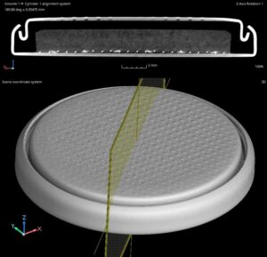
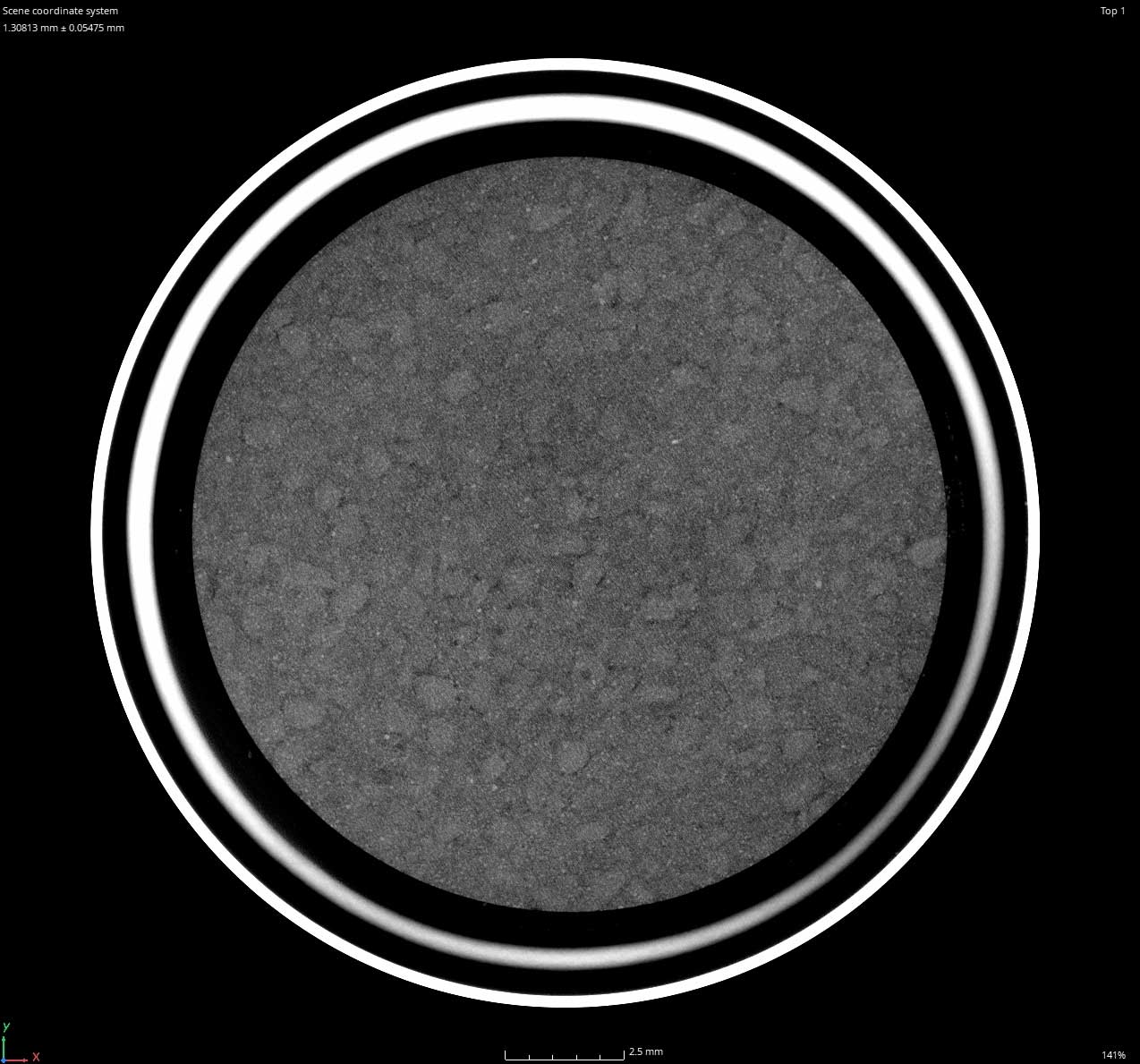
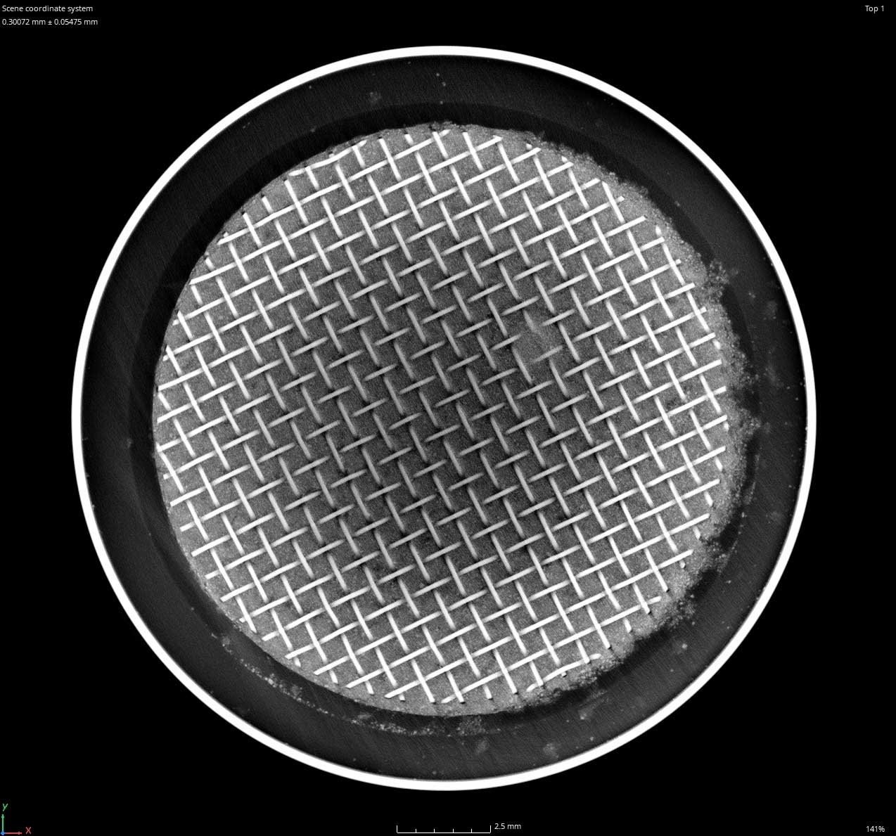
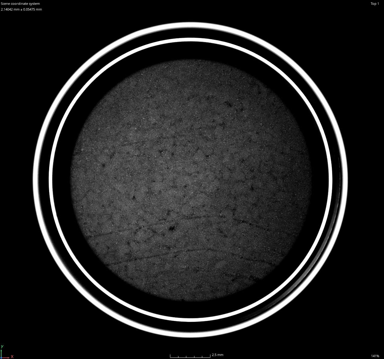
COIN & BUTTON CELL BATTERIES
Micro-CT imaging is a critical tool for characterizing the geometry of small batteries. With variable resolution between 3um and 125um, no battery is too small to be imaged.
CT characterization is used for evaluating new technologies, comparing process changes, and determining points of failure.
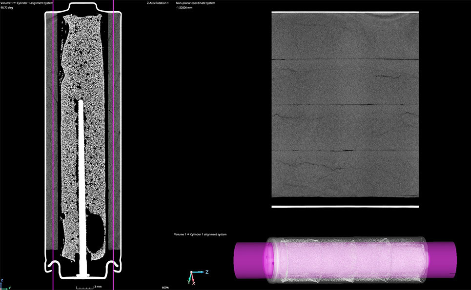
CYLINDRICAL BATTERY CELL (AA)
There are several imaging methods and variables to consider for a given application. When we scan cylindrical cells a useful tool called “Unroll” is often deployed.
Unroll allows the inspector to planarize cylinders. For example, imagine cutting a toilet paper roll and laying it flat on your desk. The digital equivalent allows the inspector to scroll through a planar view at any distance from the specified axis.
The video to the right demonstrates “Unroll.”
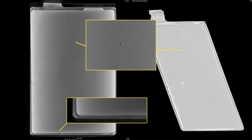
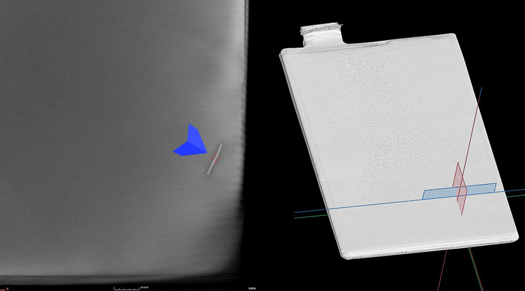
POUCH & PRISMATIC CELLS
Foreign object debris is one of the primary causes of battery thermal runaway resulting in increased temperatures, destruction of the battery, and fires.
Reliable detection of foreign objects is critical for the safe manufacture, storage, and long term use of battery cells. If there is a manufacturing failure it is best to inspect cells before assembling them into full battery modules. Because cells are smaller and easier to handle resolution and x-ray penetration can be improved.
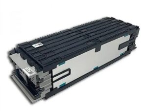
BATTERY MODULES
Industrial Inspection staff has CT scanned thousands of battery modules. Customized criteria are used for each project with regard to what the issue may be. Some typical rejectable indications include:
Industrial CT scanning is used to inspect advanced materials for defects like porosity, inclusions, cracks, delaminations, and fiber orientation.
These are aircraft phenolics and their structural integrity is paramount. Pores have been located in proximity to the edge and other indications are characterized throughout the samples.
BATCH SCANNING SAVES TIME AND COST
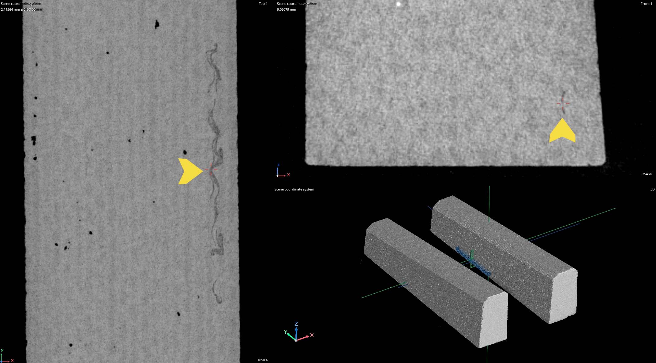
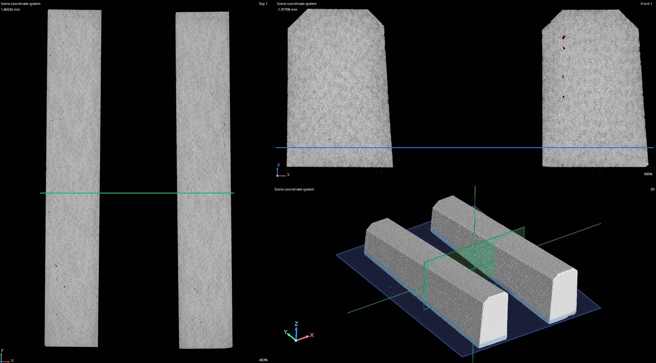
Batch scanning is a technique that can be used to scan several parts at once. This can significantly decrease required scan times and their associated cost. The two samples below were scanned next to each other and separated in Volume Graphics. One drawback to batch scanning is the reduced resolution to fit both samples into the field of view.
Seen below is a significant linear indication found along the length of one of the samples.
CORE SAMPLE ANALYSIS
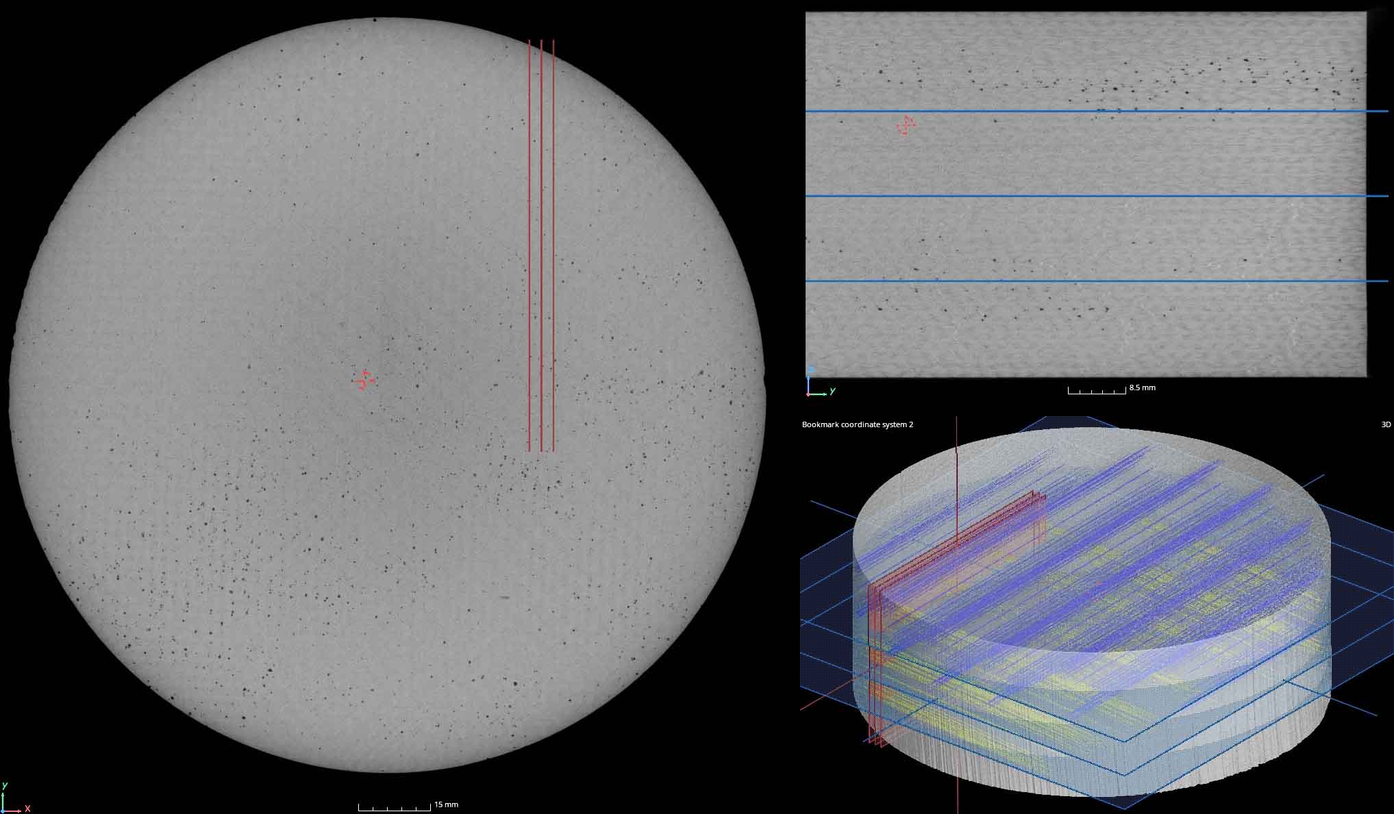
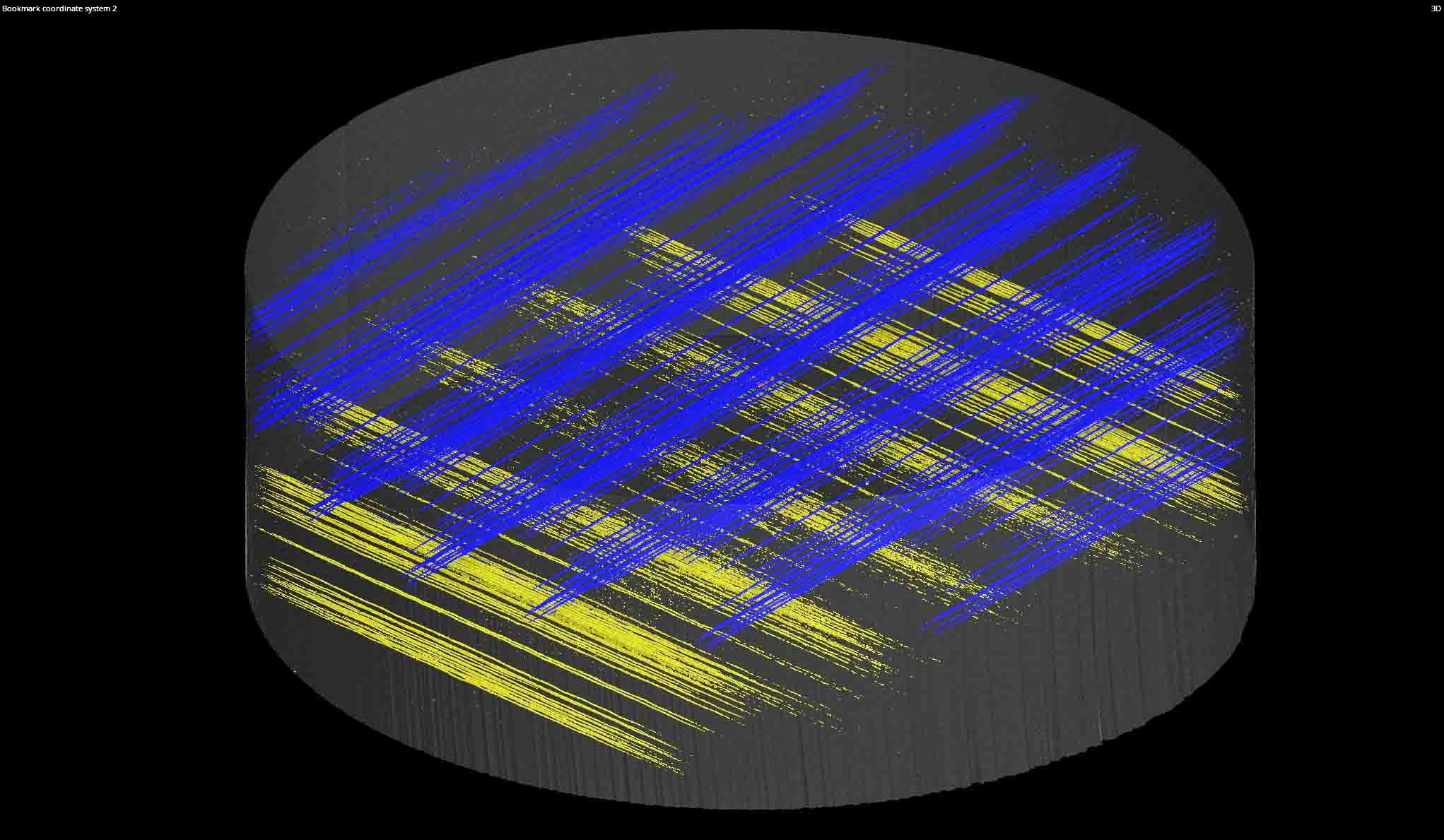
Due to penetration and volume limitations of CT scanning, core sampling is used to test a batch of much larger parts to characterize their quality. Clients may section material out of an area of interest (a functionally critical zone or area that is more prone to manufacturing flaws). These core samples are then used to qualify batches of product or compare different vendor processes or lots.
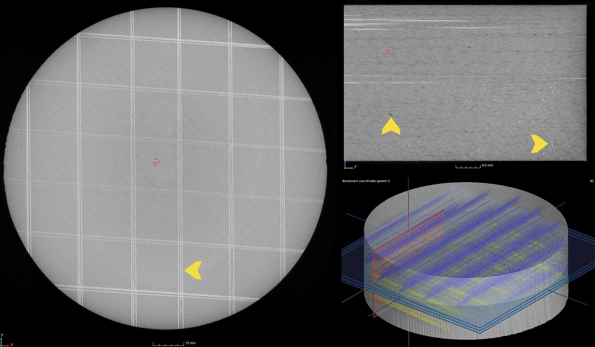
This carbon fiber sample demonstrates porosity, inclusions, and fiber orientation.
Minimum density filter showing all pores across a range
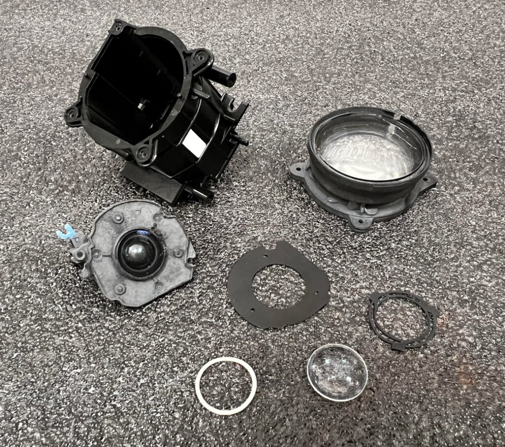
Combining high resolution scan data from devices like our Nikon CT scanners and Hexagon Laser arms with best in class inspection softwares (PolyWorks & Geomagic Design X) allows us to reverse engineer complex component and assemblies.
This multi-material camera lens zoom housing has the makings of a very difficult and time consuming project. Within the capability of CT to produce water tight scan geometry non-destructively, several of these components would need to be sectioned to acquire all necessary geometry.
There are three steps to reverse engineering:
1.ACQUIRE DATA
Data for modeling can be acquired using several methods – at Industrial Inspection we use hand tools, laser scanners, and X-Ray & CT scanners.
2.MODEL THE DATA
Part data is aligned and then designers use Geomagic Design X to sketch and blend features and correct geometries for flatness, symmetry, and patterns.
3.VERIFY ACCURACY
PolyWorks is used to compare produced models back to original scan data for accuracy and tuning.
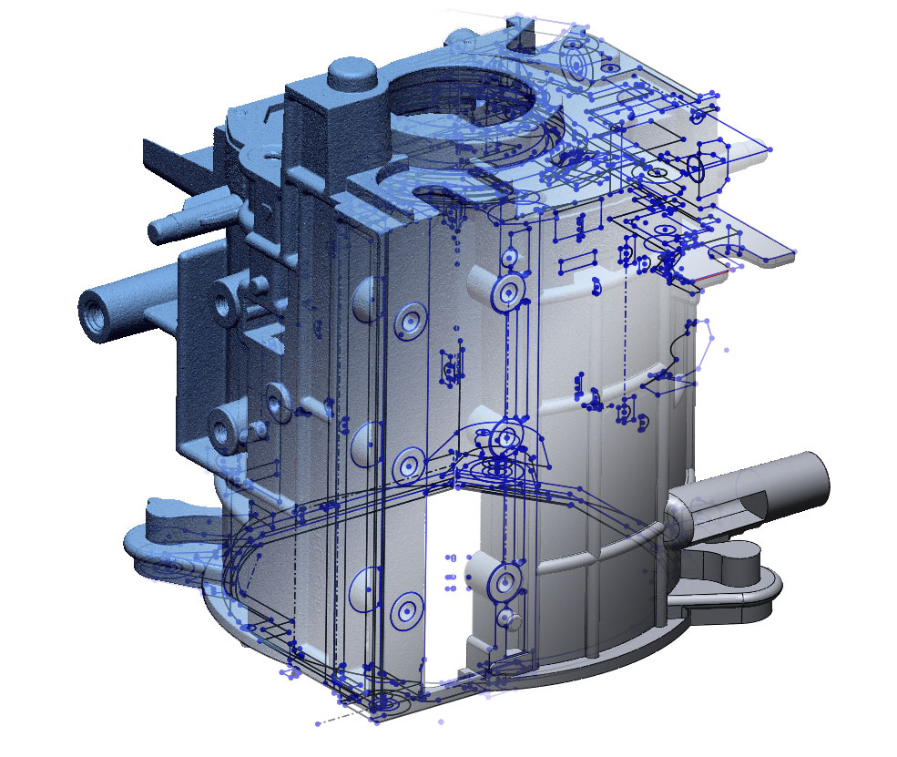
3D SCAN
2D SKETCHES
SOLID MODEL
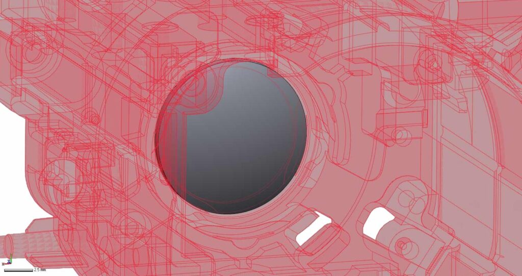
Reverse engineering lenses is particularly easy using CT technology. No spray is required like with surface scanners, and there is no noise caused by the part transparency.
One technique for modeling complex assemblies is to scan everything in the assembled state, disassemble everything, rescan the individual components, and then refit those components back to the assembly scan. This ensures everything is aligned properly and mitigates material interference so that all geometries can be modeled.
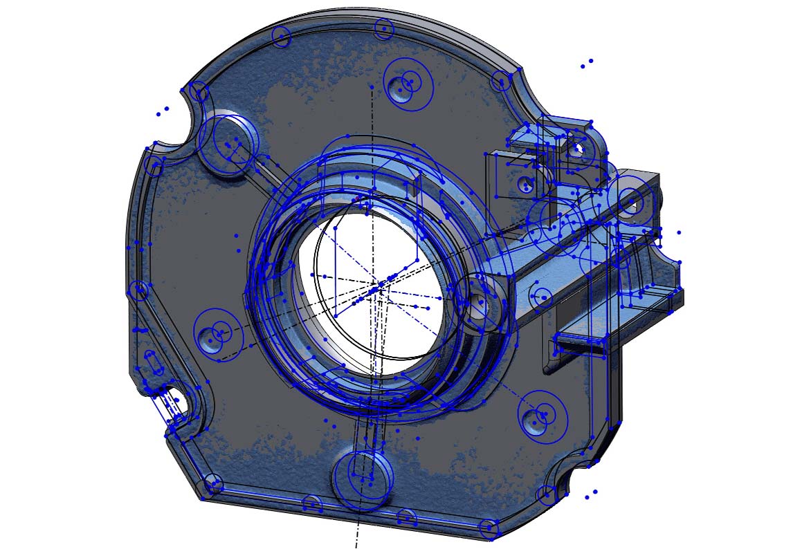
We also can use profiles from one component as a guide for additional components to minimize factors like rattling. For example, we used the ID profile of this housing as the same profile of the OD of the lens guide, ensuring a perfect fit.
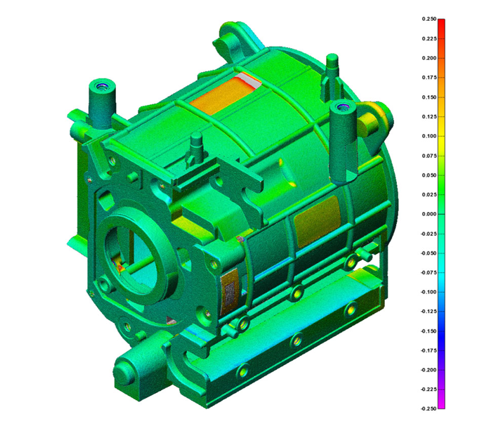
Scan to CAD profile comparisons are the critical last step of any reverse engineering job. The color coded heat map shows which surfaces are high, low, or out of position compared to the scan data. With this information the model can be tuned to an acceptable level of deviation. A report of this deviation is provided alongside the model at the end of the project.
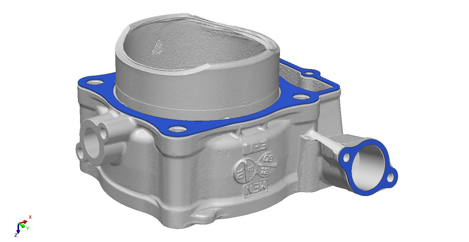
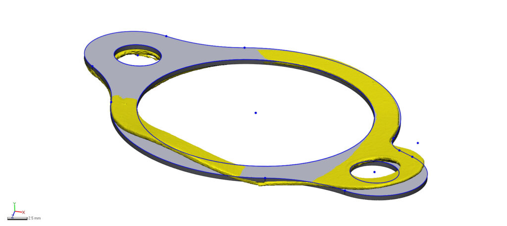
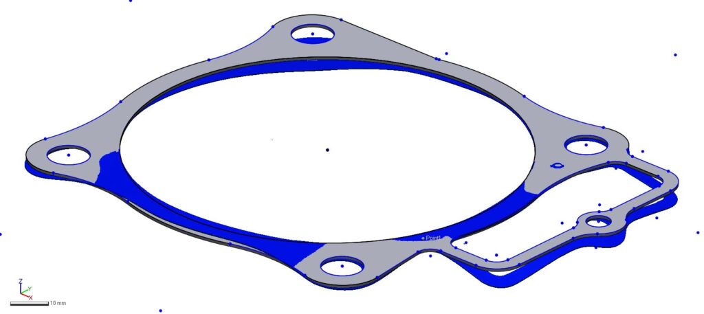
Reverse Engineering Components for Perfect Fit & Function
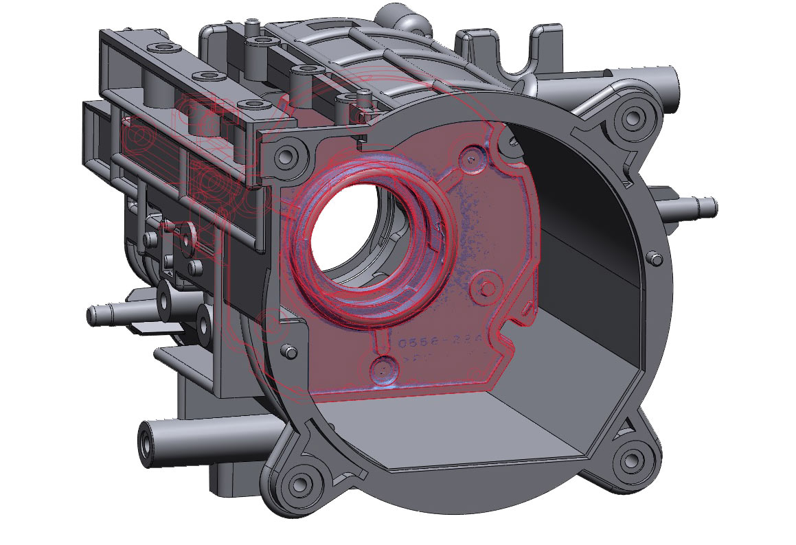
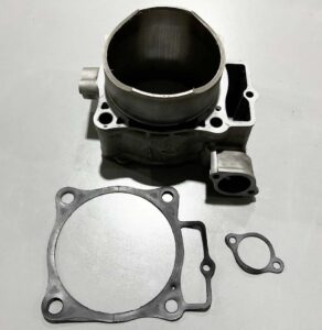
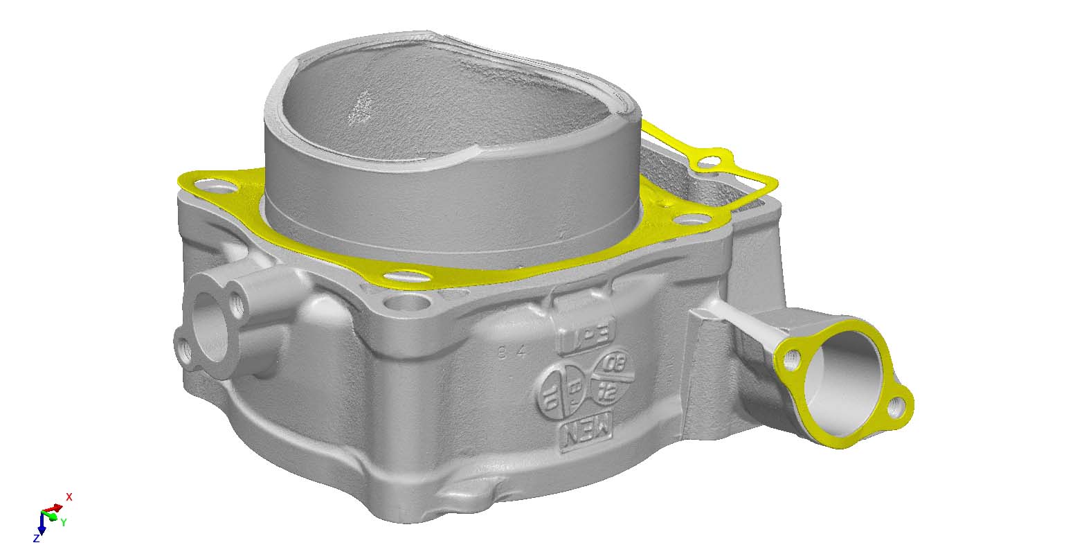
We combine exceptional technologies like CT scanning and modeling and inspection softwares to re-create perfect fit and function components. For example, these gaskets were worn and cracked and the client was unable to find replacement parts. Scanning just the casting or gaskets alone would not be adequate.
Instead, we CT scanned all three components and virtually aligned them to ensure no critical design intent was missed.
Using Geomagic Design X’s silhouette cross sectioning feature allows us to model these gaskets using the full profile of a line even though the gaskets aren’t perfectly flat. We then use the center points of the casting to ensure bolts pass through with no interference. Then, we extrude the design cross section to the exact width of the gaskets.