Skip to content
Home
About
Services
Industrial CT Scanning Services
Collectibles CT Scanning Service
Digital X-Ray Services (DR)
3D Scanning & Metrology
2D & 3D Vision & Optical Profilometer Services
Reverse Engineering Services
3D Printing & Fixturing
Dye Penetrant Testing Services (PT)
Ultrasonic Testing (UT)
Eddy Current Testing Services
Visual Testing Services (VT)
Magnetic Particle Testing Services (MT)
NDT Consulting & Oversight
Training & Certifications Services >
Training Course List
X-Ray Film & Image Review Services
Resources
Case Studies
Industrial CT Scanning Case Studies
Industrial X-Ray Case Studies
3D Scanning & Reverse Engineering Case Studies
Guides
X-Ray Safari
Contact
sales@industrialinspection.com
(231)246-8473
Category: X-Ray & CT Scanning
Barium Contrast Agent for Xray & CT Imaging Enhancement
July 17, 2025
/
X-Ray & CT Scanning
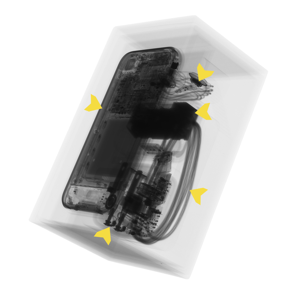
Authenticating 1st Generation 2007 iPhones using X-Ray & CT
July 1, 2025
/
News
,
X-Ray & CT Scanning
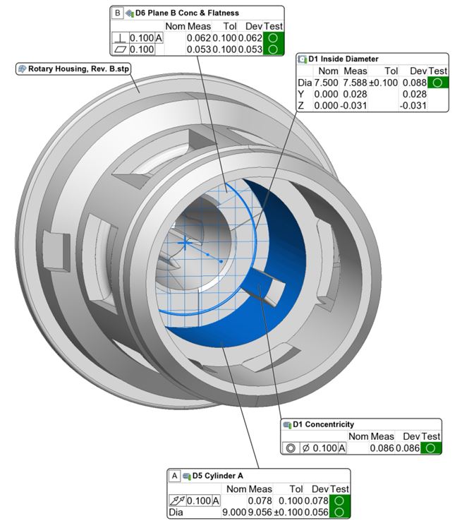
Dimensional Repeatability using CT Scanning
June 25, 2025
/
3D Scanning & Dimensional
,
X-Ray & CT Scanning
Industrial Inspection: Switch 2 X-ray & CT
June 4, 2025
/
X-Ray & CT Scanning
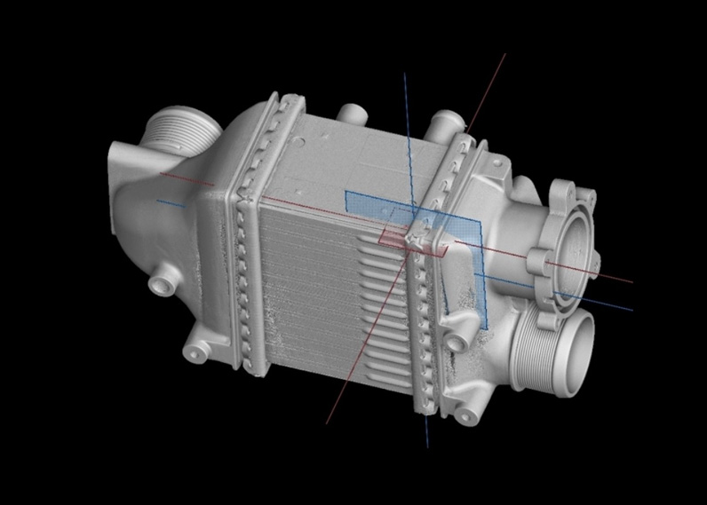
CT Scanning Aluminum Charged Air Cooler for Leaks
May 31, 2025
/
X-Ray & CT Scanning
CT Scanning Fuel Injectors for Injector Angles
May 29, 2025
/
X-Ray & CT Scanning
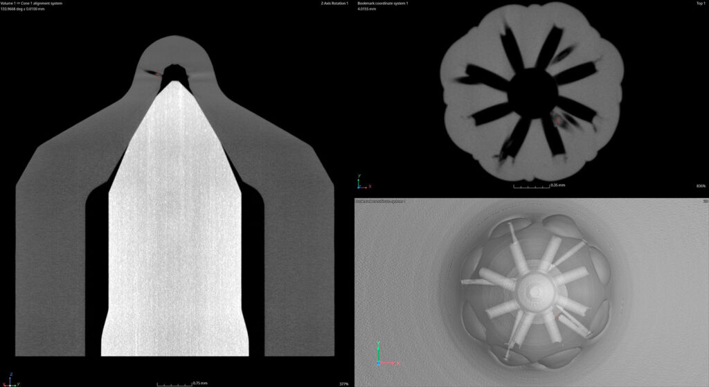
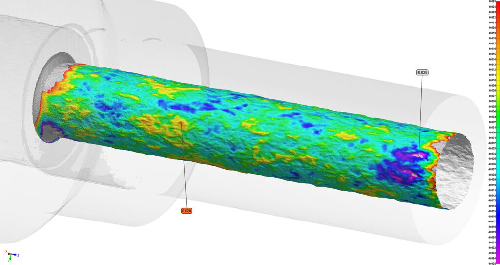
CT Scanning Steel Microfluid Assemblies for Cracks & Profiles
May 28, 2025
/
Vision & Surface Roughness
,
X-Ray & CT Scanning
IIC Launches X-RAY Authority
May 15, 2025
/
Collectibles Library
,
News
,
X-Ray & CT Scanning
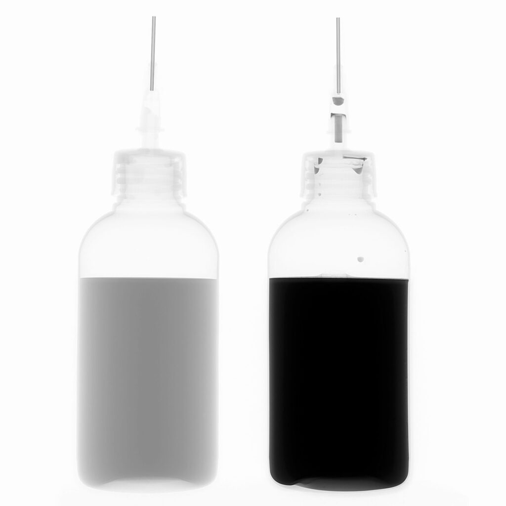
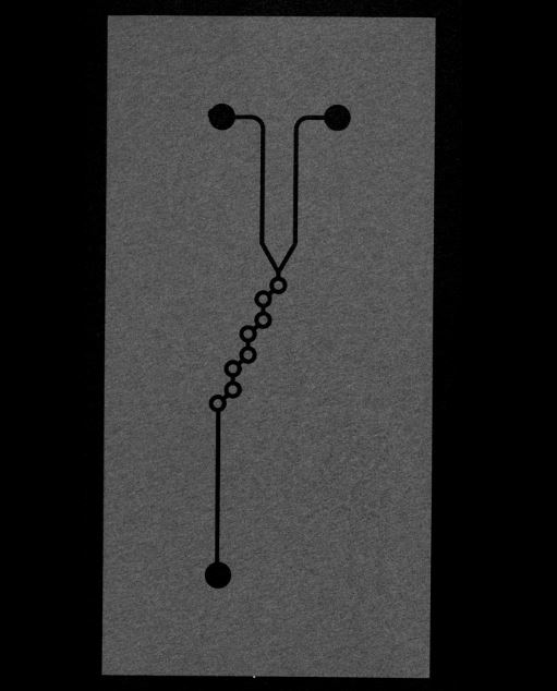
Inspecting Microfluidic Mixers
May 10, 2025
/
X-Ray & CT Scanning
CT Scanning 3D Printed Steel Tooling for Leak Paths
May 3, 2025
/
3D Printing
,
X-Ray & CT Scanning