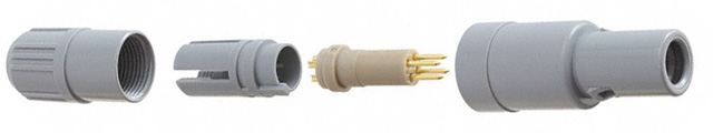
With advanced technologies we turn physical parts into digital formats including .stl & .step. This case study focuses on the reverse engineering workflow, so to understand what reverse engineering is used for visit our Reverse Engineering Page.
>HIGH QUALITY DATA MATTERS
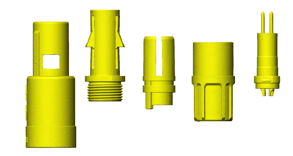
Accurate and complete data sets allow technicians to build complex models with better design intent – from complex coordinate systems to informed decisions about deviation corrections. Our laser and CT scanners produce high accuracy and water-tight geometry.
>>APPLYING BEST DESIGN PRACTICES
Our models are produced by experienced design engineers. They apply both GD&T theory and practical experience to every surface. Their experience means our cost per model is the most competitive on the market. How? Because we are fast, accurate, and have reproduced just about every type of product imaginable.
>>>END RESULT: TOOLABLE MODELS
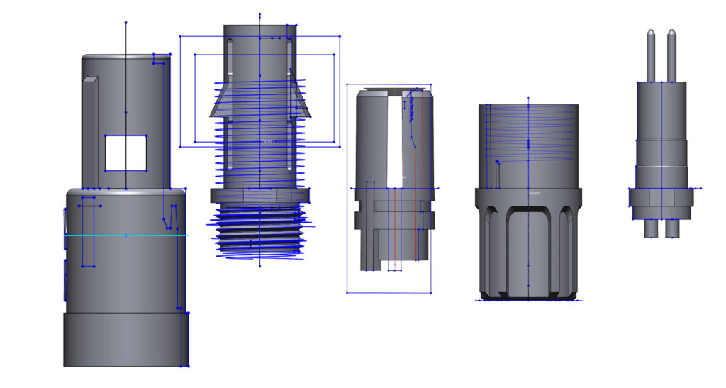
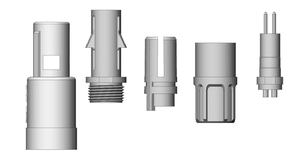
Final models are sent in universal formats such as .step or .iges. The parametric datasets include deviation corrected geometries – planes are made flat, symmetry is mirrored, & hole patterns rounded to equal size. Complex assembly models can be produced in common coordinate systems with gauranteed fit.
>>>>WE CHECK OUR WORK FOR YOU
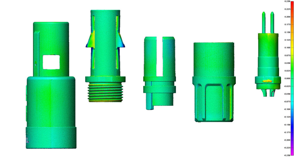
Every model that is produced is compared back to the original scan data. A report is included with each model which contains profile deviation maps. Proud or shy surfaces correspond to the heatmap. Sometimes this deviation is by design to correct warp.
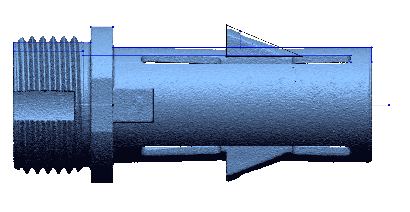
>>>>>CORRECTIVE ACTION INCLUDED
This part has a variety of complex features like OD & ID threads. It also has clips with little support structure. Because of this lack of support they have warped inward. By using the surrounding geometry we can determine the offset required to bring the clips back to a design intended location. The black cross section shows where the final geometry will be.