Inspection requirements and services are often considered “non-value added” because they cost money and could cause delays if the products do not meet specifications.
But, what if inspection services can be Value Saving?
Some parts we inspect are safety and mission critical. Other times, only a handful of parts are available and to produce more would require significant tooling and development costs. These parts could take months and many thousands of dollars to produce. If inherent, latent defects are causing significant scrap rates, we offer a way to accurately define the exact location of each defect within a part. By physically pinpointing exact defect locations and depths, we assist manufacturers in their re-work operations which can significantly reduce wasted material, cash, and production timelines.
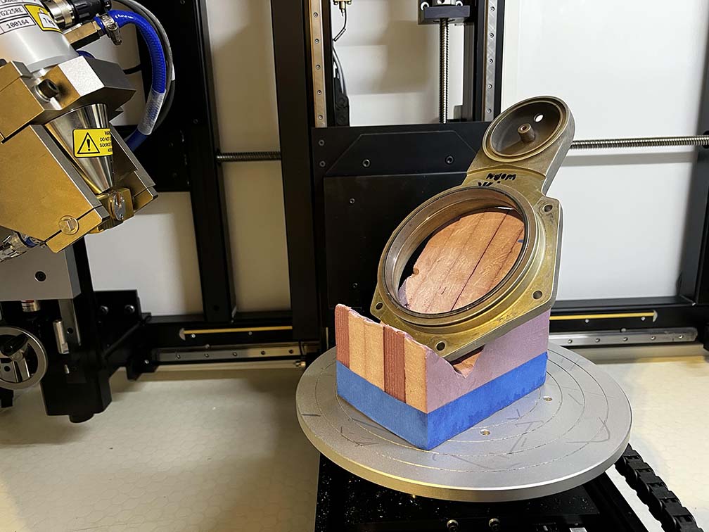
Step 1: CT Scan the Product
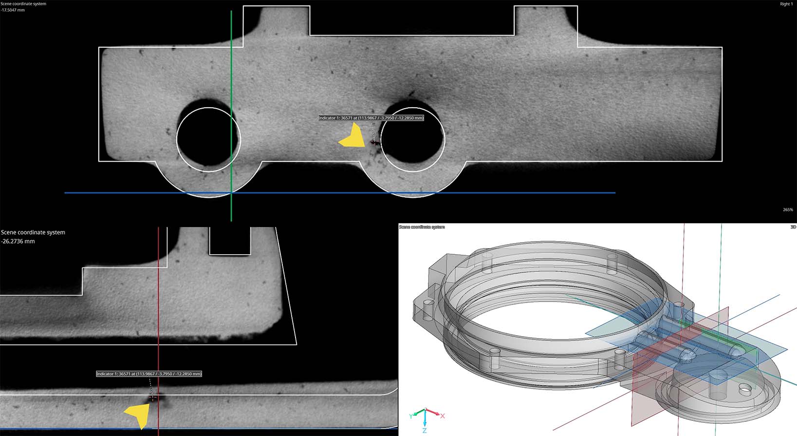
The first step in this process is to collect CT scan data of the part. The CT data is then aligned to a CAD model. The origin and coordinate system of this CAD model is critical for the next steps. Once the CT scans are aligned to CAD our team of ASNT / NAS410 radiography specialists review the data and notate any rejectable indications. Volume Graphics indication points produce XYZ coordinates relative to the coordinate system of the project scene and coordinate system. We then export these indication coordinate points into a separate file.
Casting defects are particularly important if they are in high-stress zones, or near machined surfaces. We can determine if these defects are in these zones, and even modify CAD for boundary acceptability tolerancing. For example, the manufacturer may find defects acceptable up to .5mm from a machined surface. We can offset CAD surfaces by .5mm for an objective indicator of rejectability.
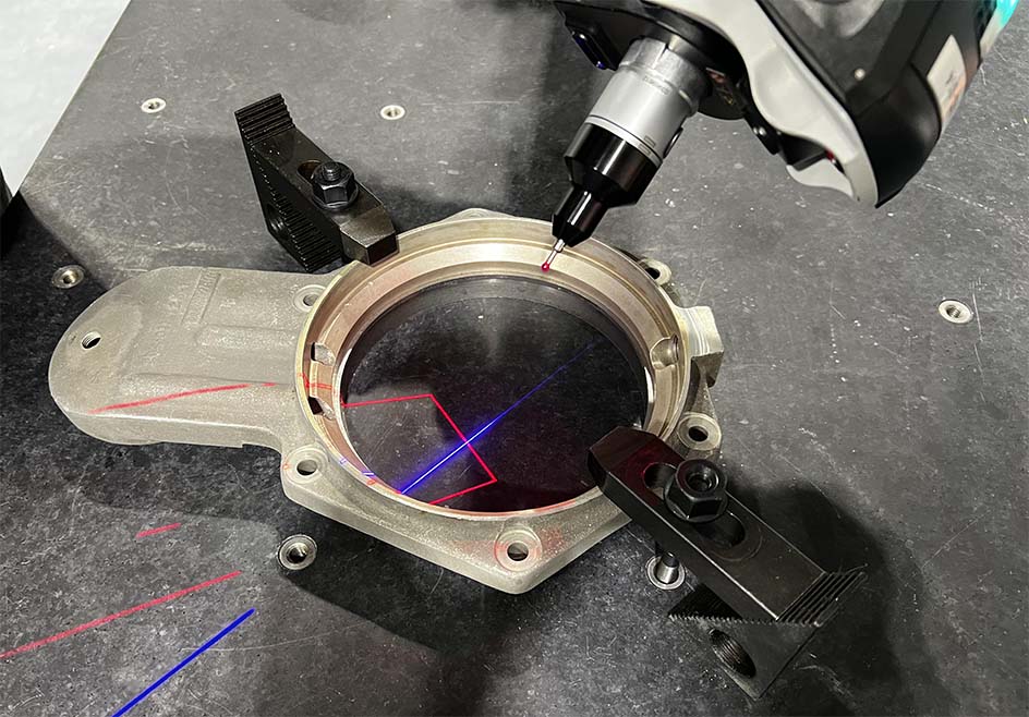
Step 2: LASER SCAN THE PART
The second step of this process is to laser scan the part. Once data is captured we align the scan to the same CAD model used in Step 1. Then, we import the indication coordinate points into PolyWorks.
Step 3: PROBE THE DEFECT
The third step of the process is to locate the indication coordinate points using the the probe of our laser scanner. Once the probe is within an allowable distance of the actual indication, the zone turns green.
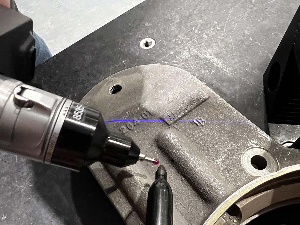
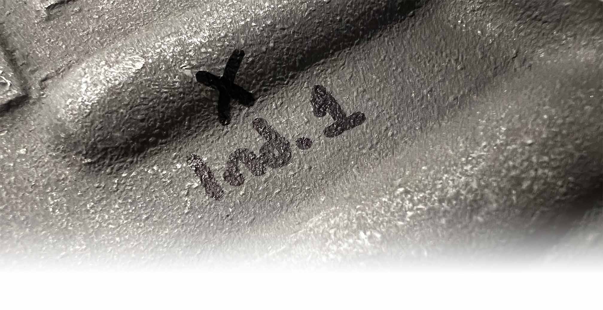
Step 4: MARK THE DEFECT
Once the probe is within the acceptable zone of the indication, the technician uses their other hand to physically mark the indication defect on the part with a marker or paint pen. Then, manufacturers can machine or drill out the location and weld the geometry back for a defect free product.