In just a few steps you can become an expert CT analyst. This guide demonstrates the basic, step-by-step functions of the industrial CT industry’s standard software: Volume Graphic’s myVGL Viewer.
1.Download myVGL & Open File
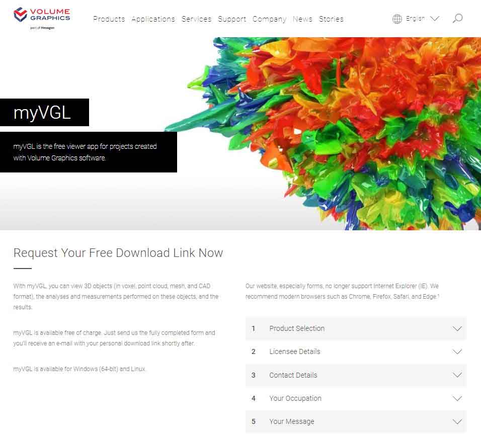
myVGL is the free viewing app for projects created with Volume Graphics Software.
With myVGL, you can view 3D objects (in voxel, point cloud, mesh, and CAD format), the analyses and measurements performed on these objects, and define your own measurements and imaging results!
2.ACTIVATE NECESSARY TOOLS
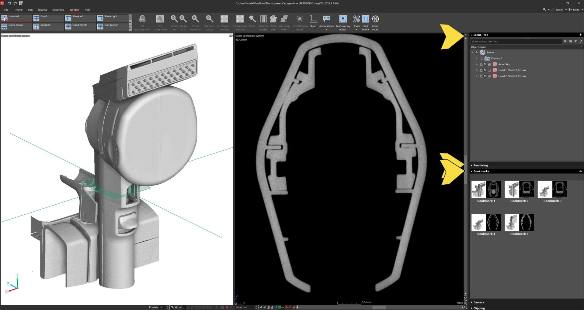
Navigate to the Window pane. To the right, click the “Tools” drop down to activate important sidebar options like Rendering, Scene Tree, and Bookmarks.
Rendering allows for contrast adjustment, Scene Tree shows the different files and tools within the project, and Bookmarks allow you to navigate between saved images.
3.NAVIGATION
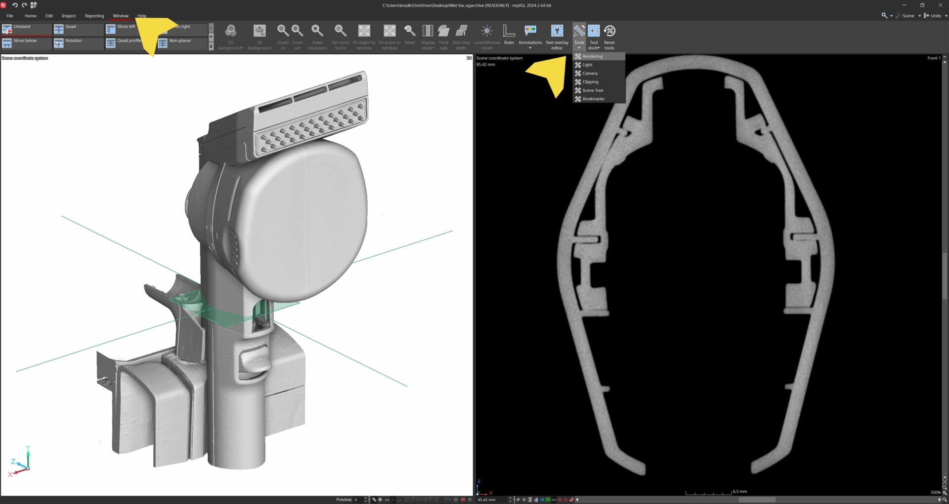
Clicking the cursor navigation button in the upper left corner allows the user to navigate to a single location in all window views simultaneously. Hold Ctrl + Left Click any location.
In the Window menu the viewing panes can be modified or removed for optimal viewing of areas of interest. Quad View is standard which shows all three planar directions and a 3D render view in the bottom right. Additional options include Rotational View about an axis, or Unroll View which planarizes cylindrical features.
4.CONTRAST & RENDER ADJUSTMENT
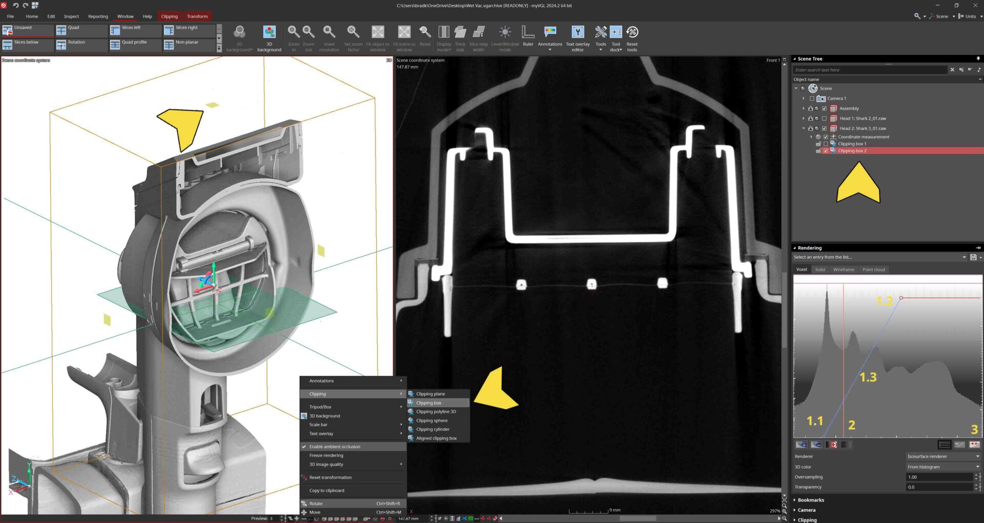
Adjusting the contrast of the scan data is done in the Rendering window you activate earlier. The Histogram contains a variety of tools including a sliding bar. At the ends of the bar are upper and lower limit handles (1.1 and 1.2). Drag these to adjust the contrast. You can move both handles simultaneously by selecting and dragging 1.3. Location 2 shows the Gray Value rendering slider and Location 3 activites and deactivates the ability to adjust the Gray Value rendering slider.
Right clicking the 3D renderopens a menu with a variety of options including clipping tools. Clipping tools can be used to digitally section the part, and the sections are saved to be activated or deactivated in the upper right Scene Tree.
5.SLICE SETTINGS
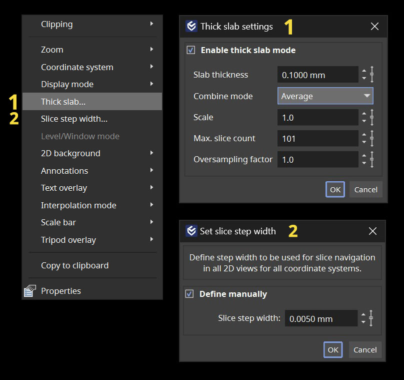
Right click any viewing pane to open pane settings menu. Primary viewing tools including:
Thick slab – the slice thickness control which has parameters to define thickness, bring forward the highest density gray values in that thickness, slice averaging, and so on.
Slice step width – how far the viewer scrolls through each tick of the mouse. The small the value, the slower the scroll and more detail will be viewed.
6.MEASUREMENTS
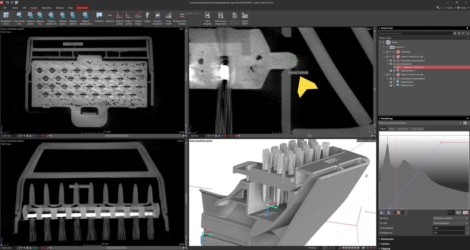
A variety of measurement options are available in myVGL including basic dimensioning like distances, angles, and polylines. However, complex dimensional tools like profiling, wall thickness, CAD alignments, and coordinate systems are reserved for full Volume Graphics Cast & Mold licenses.
Indicators are used to mark areas of interest and recover their locations quickly. Calipers use rendered surface data to create tangible distance measurements.
Clip Depth Measurement
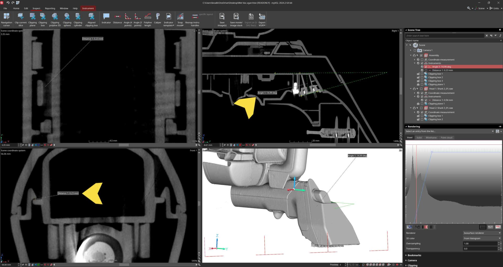
Tube Angle & Clip Gap Measurement
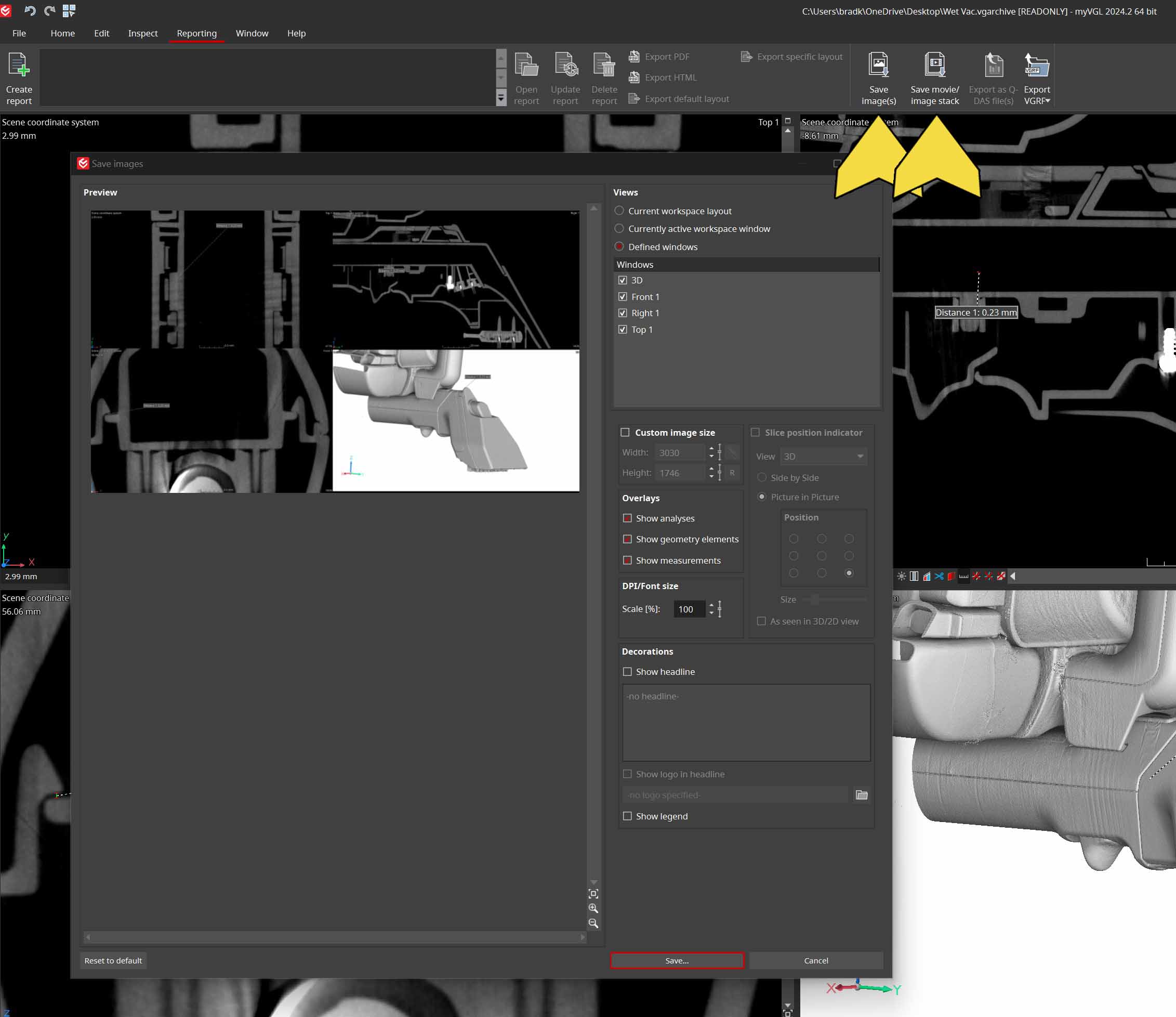
7.IMAGING & REPORTING
In the Reporting panel measurements can be exported to Excel and images can be exported using the Save Image button. Images can be modified based upon the current state of the defined windows of the software or as defined in the Save Image pane.
2D slice videos can also be exported.
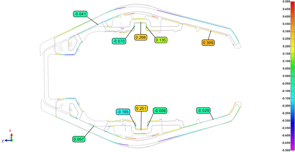
8.METROLOGY USING POLYWORKS
Visit our case study about dimensional inspection of these vacuum heads using PolyWorks Metrology Suite here.
Complex dimensional programs can be written for large batches of parts for GD&T and profile analysis.