Laser & CT scanning produces high accuracy, water tight digital representations of products to be used for part to part and part to CAD dimensional inspection.
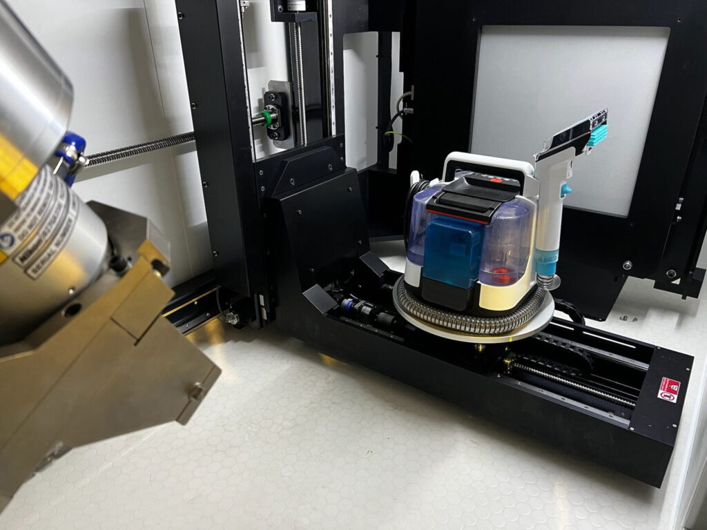
This case study demonstrates the measurement of slop between two wet vacuum attachments. One attachment was noticeably looser than the other but defining exactly where would not be possible without mapping the entire mating point.
Data was acquired in our Nikon Industrial CT Scanner, exported to .STL, and imported into PolyWorks Metrology Suite for dimensional comparison.
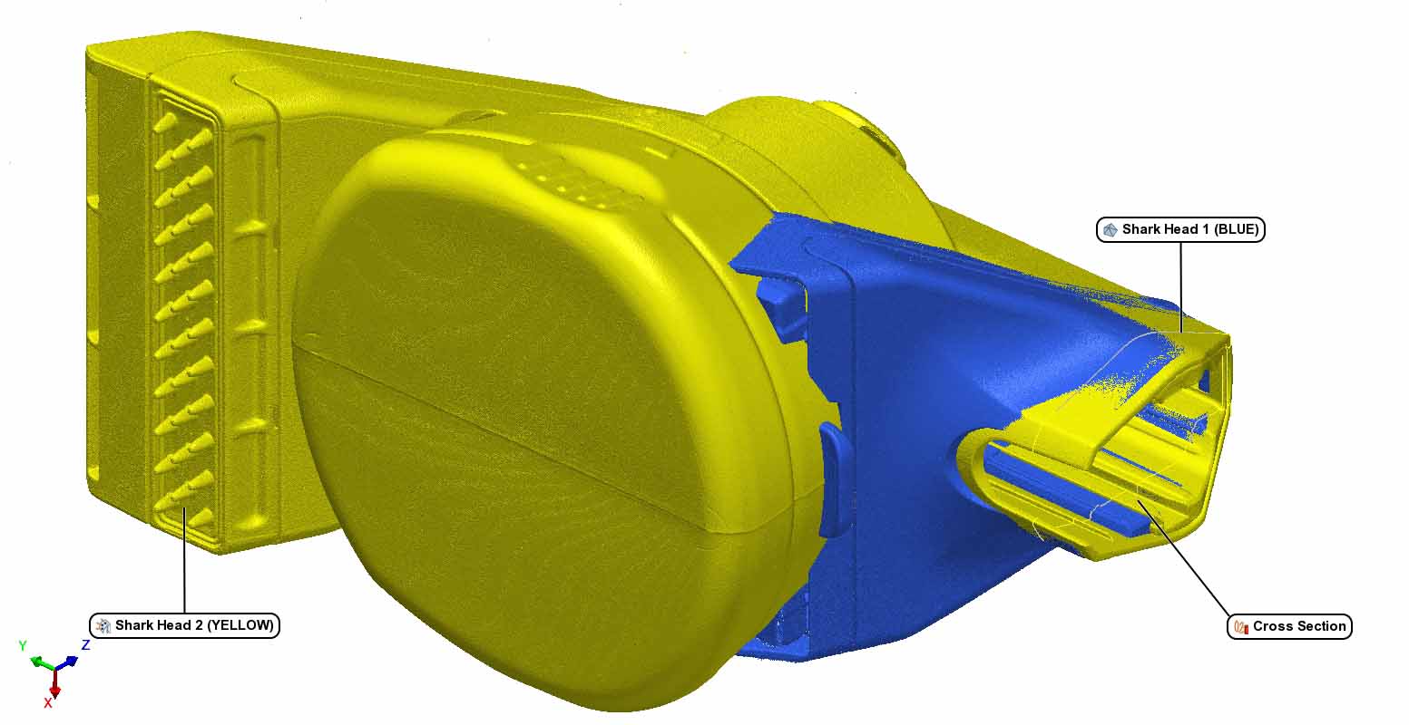
HEAD 2 ALIGNED TO HEAD 1
A local best fit of the mating zones was created and a cross section was placed at the area of interest: the plunger and rib track which aligns the head to the hose.
HEAD 2 ALIGNED TO HEAD 1
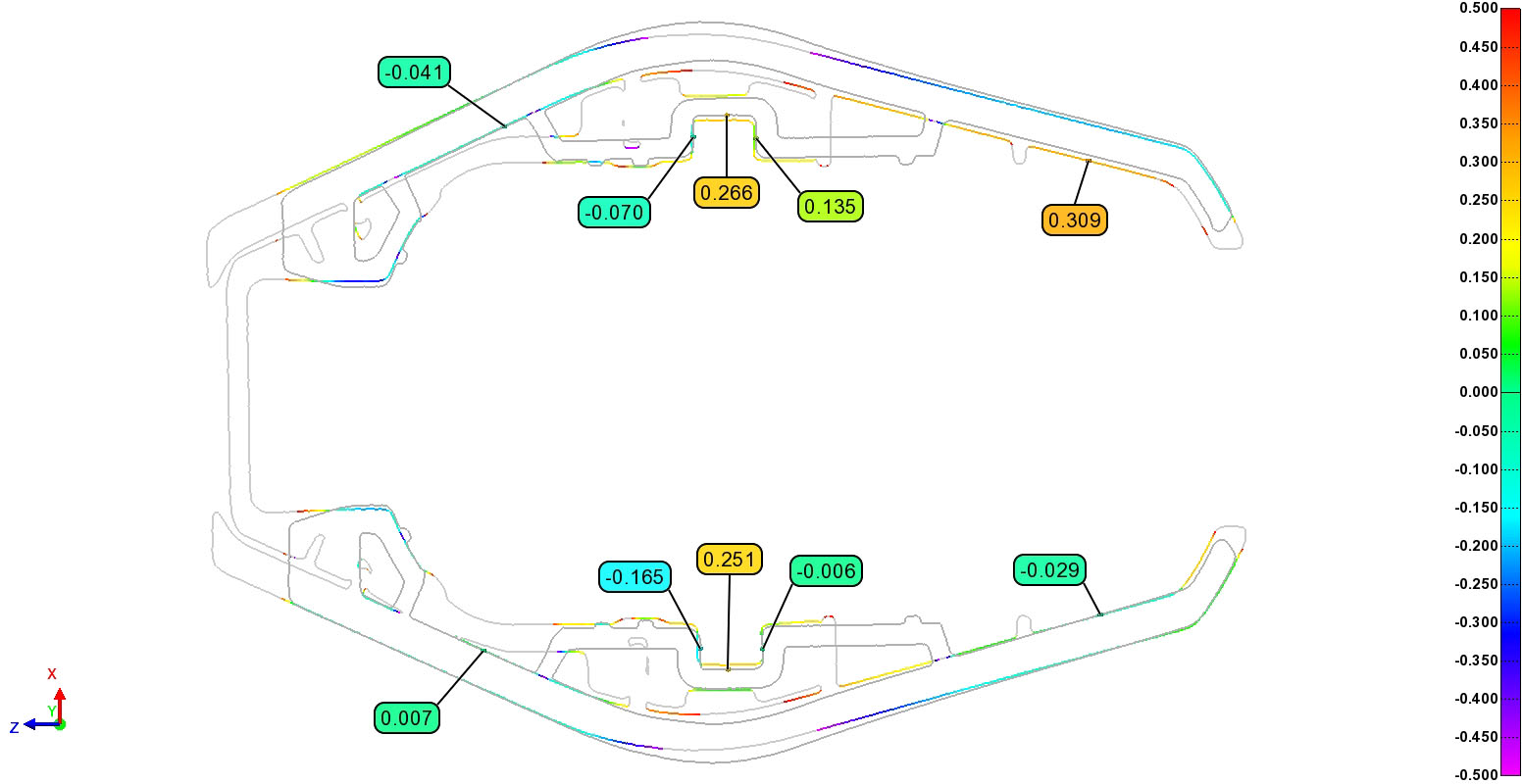
The 2D cross section provides a color-coded profile of a line heatmap. Green to Red colors indicate the “compared” geometry is positive (proud) compared to the reference geometry, while Green to Purple colors indicated geometry is negative (shy) compared to the reference geometry. This tells us the loose fitting head has a larger profile than the tight head and can help engineers tune their molding process.