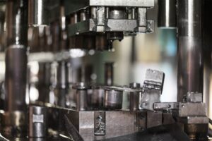
Scanning technologies are used to reverse engineer tooling die steels. Over time steel wears, breaks, or is modified to produce a better part. Design files become lost or do not match the modifications.
Using our high resolution laser pCMM we can reproduce worn die steels into toolable .step CAD models.
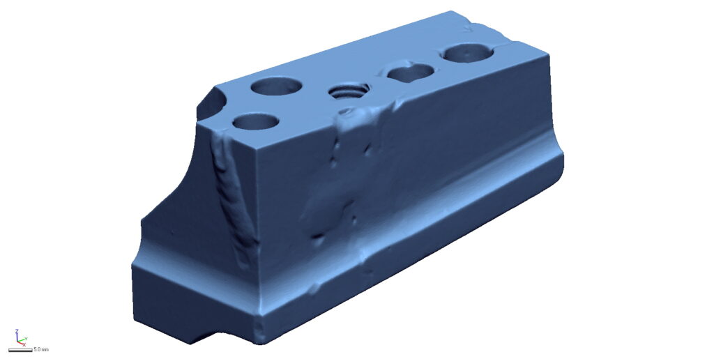
STEP 1ACQUIRE SCAN DATA
Lorem ipsum dolor sit amet, consectetur adipiscing elit. Ut elit tellus, luctus nec ullamcorper mattis, pulvinar dapibus leo.
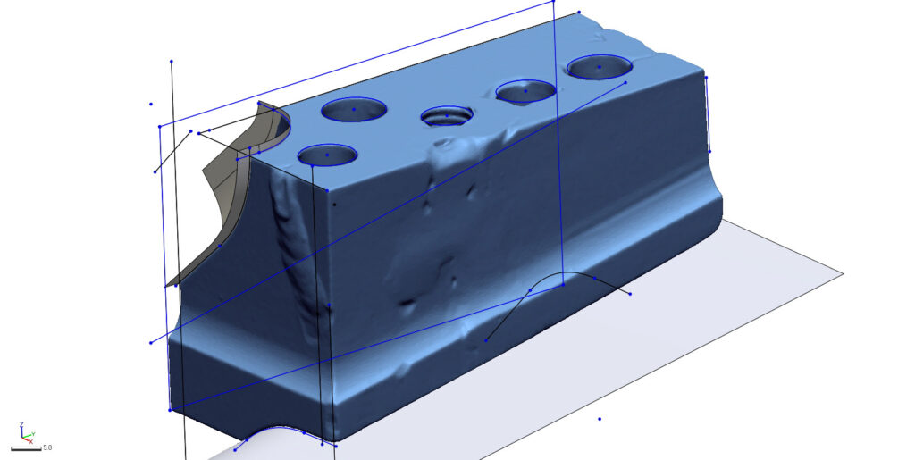
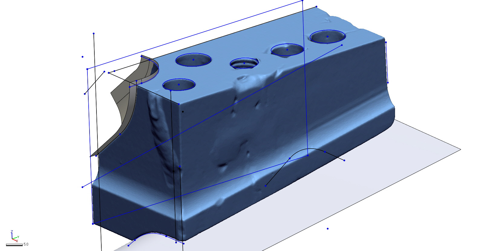
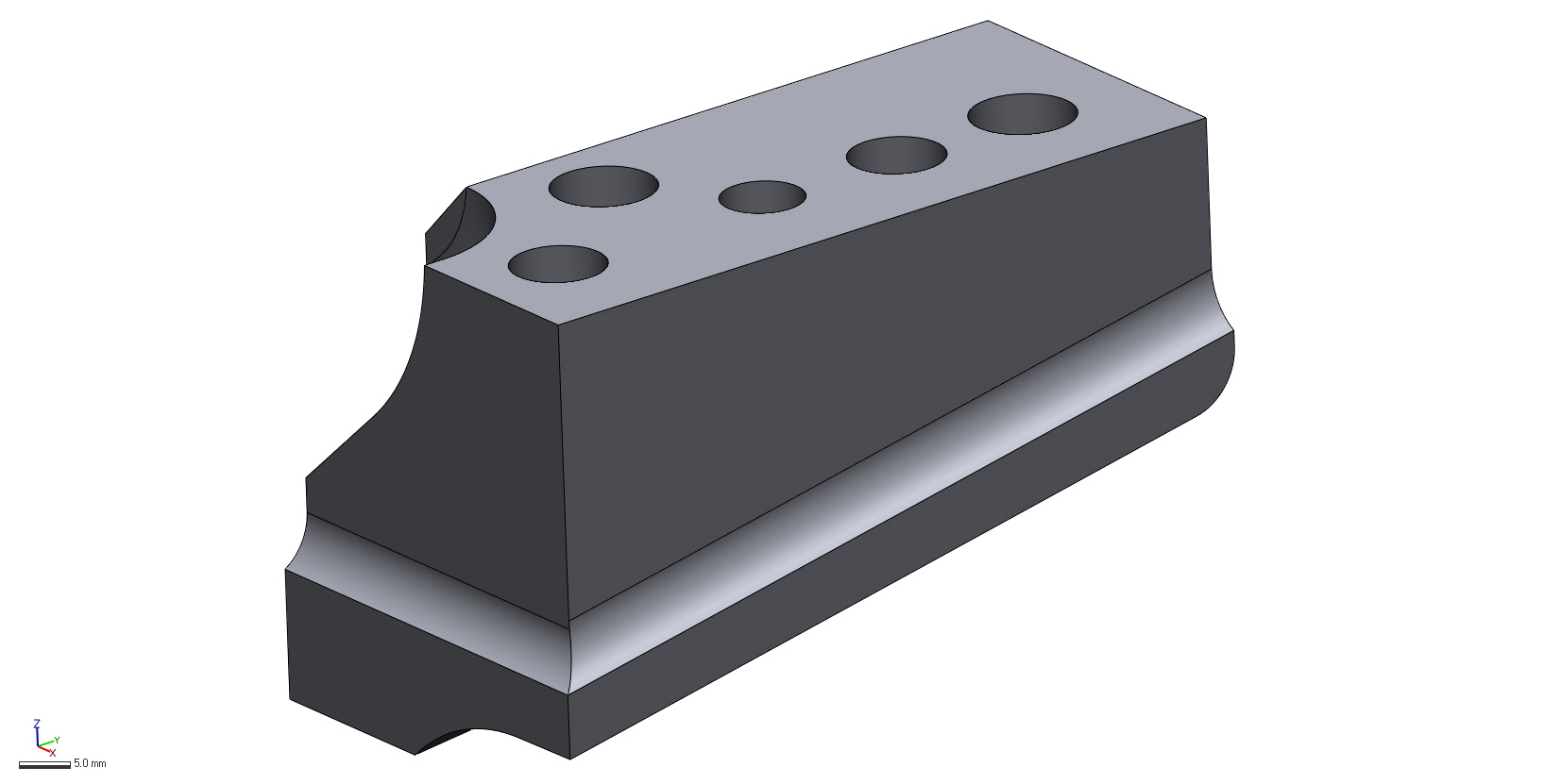
STEP 2SKETCH THE GEOMETRY
Geomagic Design X offers a large variety of modeling tools like 2D sketching, extrusions, lofting, patterning, and symmetry.
Assets are created and merged into a solid model.
STEP 3TUNE THE MODEL
After a model is created it is tuned to achieve the minimal amount of deviation. Sometimes surfaces need to be moved or hole sizes adjusted.
STEP 4REPORT THE DEVIATION
The deliverables for every reverse engineering project include a final .step model as well as a deviation report. This profile heat map shows the areas where the produced model differentiates from the original scan file.
Sometimes deviation is inevitable where a cracked component was stitched back together, while other times a free-form surface cannot be perfectly geometrically replicated.