Reverse Engineering Complex Assemblies
Combining high resolution scan data from devices like our Nikon CT scanners and Hexagon Laser arms with best in class inspection softwares (PolyWorks & Geomagic Design X) allows us to reverse engineer complex component and assemblies.
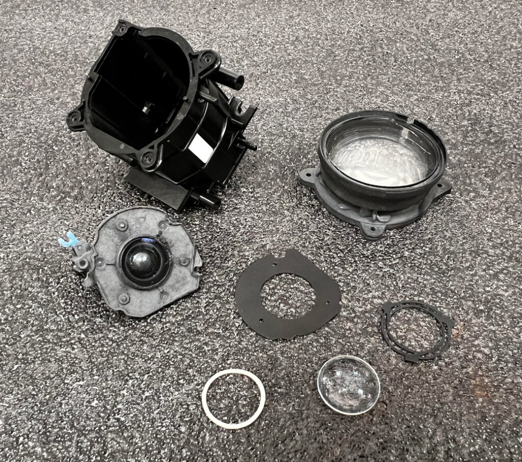
This multi-material camera lens zoom housing has the makings of a very difficult and time consuming project. Within the capability of CT to produce water tight scan geometry non-destructively, several of these components would need to be sectioned to acquire all necessary geometry.
There are three steps to reverse engineering:
1. ACQUIRE DATA
Data for modeling can be acquired using several methods – at Industrial Inspection we use hand tools, laser scanners, and X-Ray & CT scanners.
2. MODEL THE DATA
Part data is aligned and then designers use Geomagic Design X to sketch and blend features and correct geometries for flatness, symmetry, and patterns.
3. VERIFY ACCURACY
PolyWorks is used to compare produced models back to original scan data for accuracy and tuning.
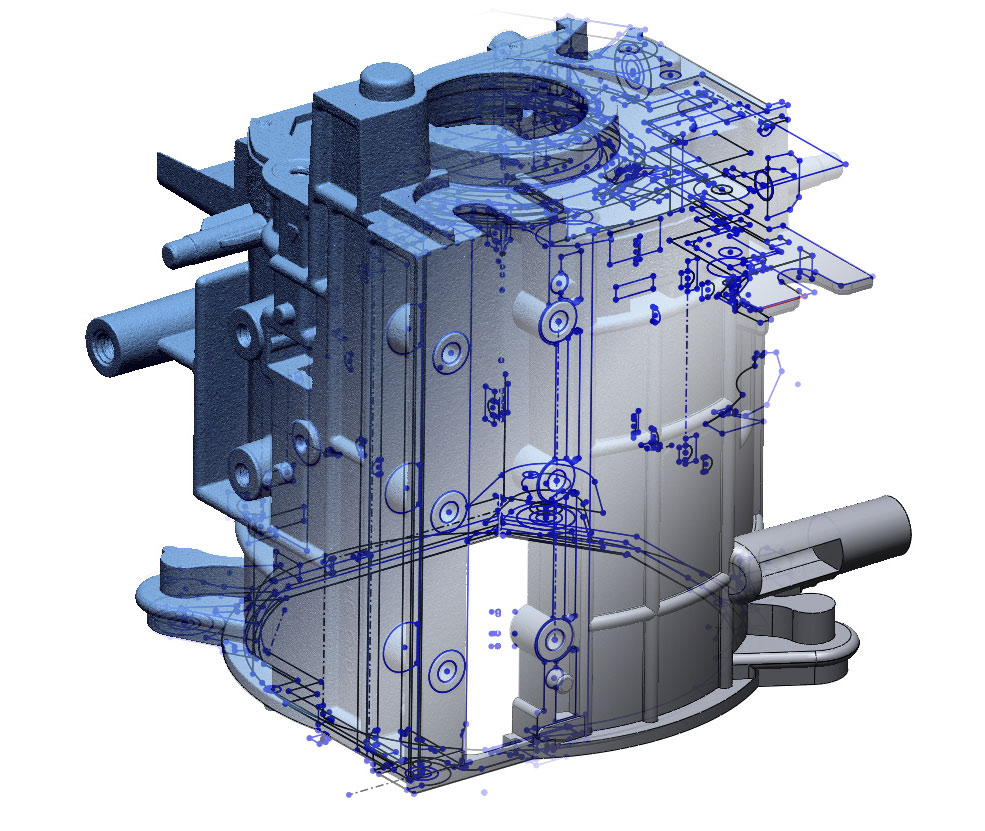
3D SCAN
2D SKETCHES
SOLID MODEL
Reverse engineering lenses is particularly easy using CT technology. No spray is required like with surface scanners, and there is no noise caused by the part transparency.
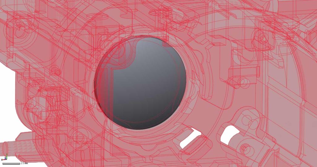
One technique for modeling complex assemblies is to scan everything in the assembled state, disassemble everything, rescan the individual components, and then refit those components back to the assembly scan. This ensures everything is aligned properly and mitigates material interference so that all geometries can be modeled.
We also can use profiles from one component as a guide for additional components to minimize factors like rattling. For example, we used the ID profile of this housing as the same profile of the OD of the lens guide, ensuring a perfect fit.
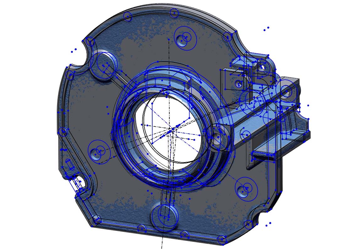
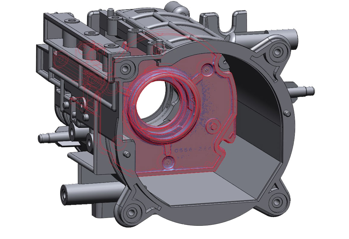
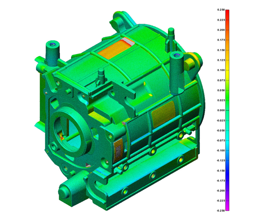
Scan to CAD profile comparisons are the critical last step of any reverse engineering job. The color coded heat map shows which surfaces are high, low, or out of position compared to the scan data. With this information the model can be tuned to an acceptable level of deviation. A report of this deviation is provided alongside the model at the end of the project.
