X-ray vision is not just for superheroes. We, the scrawny nerds, can see inside objects to offer you a variety of services like non-destructive testing for R&D and part conformance qualifications, dimensional inspection of complex, inaccessible geometries, and reverse engineering of those same geometries for applications like FEA, historical part documentation, and re-engineering a product that works better than its original design.
Applications include everything from looking for leaks in packaging to sorting or aircraft sensors for debris.
>> Industrial Radiography
This demonstration part is an aircraft pressure sensor which is used to turn flight control components and indicators on and off. A perfect part is required to guarantee the safety of people and missions, and without x-ray it’s not possible to evaluate certain requirements. The below digital x-rays show the same part but from two perspectives. The first shows a straight-on view allowing us to learn things like wire integrity and spring orientation. However, without an alternative perspective, a significant and potentially objective-altering defect could go undetected. In this alternate view we detect high density debris (FOD) which could cause part and system failure if it were to lodge into working components.
[HOVER]
>>> INDUSTRIAL CT SCANNING
Radiography is used for 2D inspections while CT scanning (360 degrees of x-rays processed into a 3D file) is used for more complex part interrogations. For example, porosity can be extracted for exact pore volumes, locations, and clustering, wall thickness and thinning can be evaluation, and geometry inspected at exact reference locations. While CT evaluation is more comprehensive, it time and data intensive and thus more costly.
Component Evaluation
Foreign Object Debris (Inclusion)
Weld Evaluation - Porosity
>>>> Dimensional Inspection & Reverse Engineering
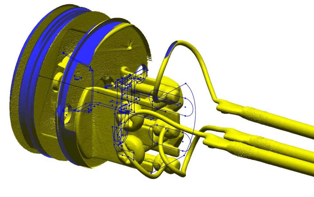
CT scan data can be exported into digital, polygonal formats like .stl, .ply, and .obj for use in softwares that can process these mesh formats. Common applications include dimensional inspection and reverse engineering. However, proper preparation of the file including scaling for accuracy, mesh clean up and filtering is required.
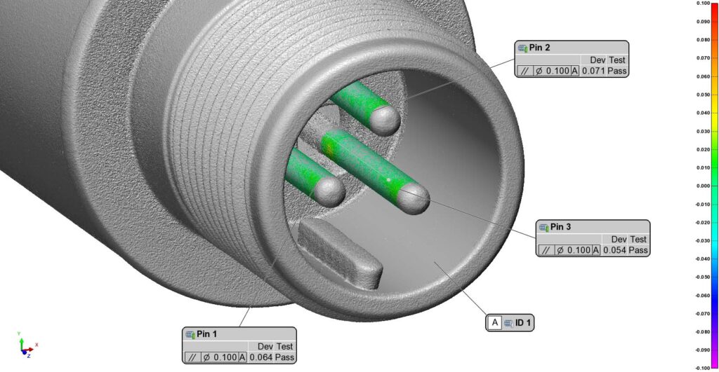
Dimensional Inspection
From basic distances like digital calipers to complex GD&T for parallelism, flatness, and true positions, we use PolyWorks for programmable dimensional inspection routines and the reporting of SPC data.
This example shows the conformance of the parallelism of the three connector pins to the A Cylinder Inner Diameter.
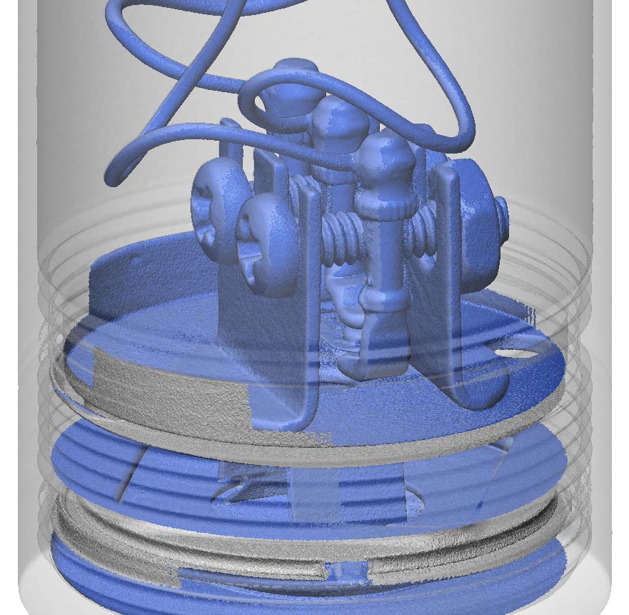
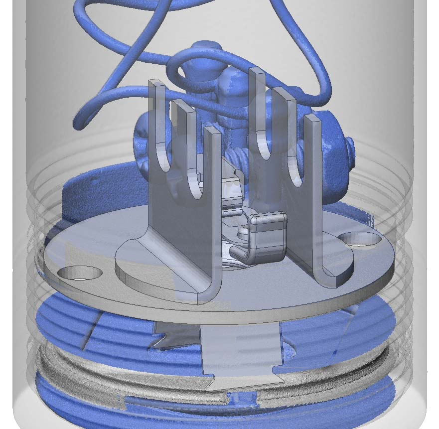
REVERSE ENGINEERING
3D scan data can be imported into Geomagic Design X for parametric model design. Geometry can be extracted with accuracy from the scan data using sketches and then modeled into solid geometry. Planes can be made flat, pins made with equal diameters and parallel to each other, patterns produced, and geometries mirrored across planes for perfect symmetry.
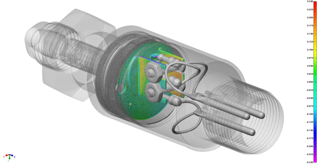
CAD Profile Comparisons
Some parts are, in fact, produced perfectly. How is this possible? While a part will always deviate from the designed geometry, if that deviation is within specification it is a “perfect” part. Sometimes drawings will specify a general profile tolerance for the entire part to ensure no considerations are missed.
Profile heat maps are direct scan to CAD comparisons. Green to Red on the scale indicates that the surface is “above” or positively deviated relative to its CAD surface while Green to Blue indicates that the surface is “below” or negatively deviated.
All reverse engineered models include a heat map displaying deviation from the actual part to the produced CAD. Sometimes deviation is intentional in order to correct manufacturing defects or part wear over years of use. Other times deviation is a byproduct of not being able to perfectly replicate complex, freeform geomtry.